Installing Optional Ceiling Closure
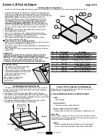
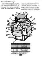
If your Scissor Lift SLX is equipped with optional ceiling closure, it can be used as is, or in conjunction with a square of existing ceiling tile (see Fig. 5)
.
1
If installing with ceiling tile, you may need to cut tile so that its overall dimensions
are the same as (or slightly less than) the closure panel. Place tile into trim frame.
Lay closure panel on top (back side) of ceiling tile, and tighten screws to hold in place.
Lipless Closure Option
is available by removing the Trim Ring from the
Closure Panel. A substrate material (ceiling tile, gypsum board, etc.) can be
attached directly to the Closure Panel using adhesive, double-sided tape or
screws.
NOTE: Make sure the added weight of the substrate does not
exceed the stated weight capacity of the lift.
Substrate should be installed
so that it is centered within the finished opening in the ceiling, with a gap of no
less that
3
/
16
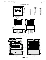
" around all edges. Lipless Closure dimensions shown with
*
in
drawing below.
2
Attach provided angle brackets to side of Bottom Panel of Scissor Lift SLX.
3
Attach threaded rods to angle bracket.
4
Run unit “up” until bottom pan stops at highest position. Mark position on
rods even with ceiling level and cut to length (remove from pan if convenient).
5
Run unit “down” until bottom pan stops at “show” position.
6
Attach closure to lower end of rods by slipping into four corner slots and
secure with nuts above and below slots.
Caution: Make sure nuts are completely tightened.
7
Run unit “up” again to highest position. Measure distance by which panel fails to
reach required “closed” height for surrounding ceiling.
8
Run unit “down” then re-adjust mounting of threadedrods in traveling grid to raise
panel required distance.
9
Test unit operation to confirm that panel will stop in closed position just before
touching ceiling.
PLEASE NOTE:
Immediately upon completion of the surrounding ceiling, unit should be
operated to confirm that optional ceiling closure panel by Draper or by
others stops
1
/
8
" short of touching ceiling in closed position. If closure panel
touches, the motor may continue operating after the lift is closed.
If it continues to cycle once the lift is closed, a motor failure may occur.
Installing Optional Ceiling Trim Kit
The Scissor Lift SLX is available with a Ceiling Trim Kit, which consists of
the lower section of the Environmental Air Space Housing and the optional
closure panel
(see Fig. 6).
1
Install Scissor Lift SLX as previously described in these instructions.
2
Install bottom section of Environmental Air Space Housing and Trim Ring in
opening. This can be accomplished by suspending with wire, or by mounting
directly to the ceiling joists (if space permits).
3
Install projector and attach optional ceiling closure to Scissor Lift SLX,
according to the instructions included in this document.
Ceiling tile
(by others)
Lower section of
Environmental Air
Space Housing
Trim Ring
Item Qty
Part number
Description
1
1
C028.546
Frame, SLX Closure Trim
2
1
C044.181.07SA
Panel, SLX Assembled Closure
3
2
C002.845.07SA
Bracket, SLX Closure
4
4 C077.035.49 Rod
3
/
8
"-16 x 17
7
/
8
" L Threaded , Zinc
5
8
C013.050
Washer .375 I.D. x .875" O.D.
x .064" TK GRD 2 Zinc Flat
6
8
C020.082
Screw, 10-16 X ½" 6 Lobe
Truss Head AB E-White
7
16 C018.027
Nut,
3
/
8
"-16 Hex GRD 2 NSF
8
4 C020.322 Screw,
5
/
16
"-18 x ¾" Long Grade 5 HH Zinc
9
4 C018.045
Nut,
5
/
16
"-18 Zinc Hex KEPS
1
2
3
8
9
7
4
7
5
6
Figure 5
Figure 6
For Additional Safety:
1
Be sure the nuts that attach the threaded
rods to the closure panel are tight.
2
Wrap a plastic wire tie around the mounting
tab and the threaded rod at all four corners
of the closure panel (see drawing).
Please Note: Do NOT use a
paper-covered or similar wire tie—
use only plastic wire ties for
maximum safety.
Scissor Lift SLX by Draper
page 4 of 8
www.draperinc.com
(765) 987-7999
Scissor Lift SLX Inspection and Maintenance
Draper recommends inspecting the Scissor Lift SLX at least annually or
every 300 cycles—whichever comes first.
A recommended maintenance schedule includes:
-
Cables:
Check for fraying.
-
Drive Chain Gears:
Check for rust, breaks, secure attachment.
-
Fasteners along scissor arm assemblies:
Make sure they are not loose. If any are loose, hand tighten the nuts.
Please Note:
There is no need to tighten nut in the top scissor which slides back and forth
in the side slot in the lift. Tightening this fasteners assembly will cause the unit
to lock up and lead to damage to the unit.
-Closure:
Make sure threaded rod remains seated firmly in the closure panel
corners, and that nuts remain tight. If they are loose, tighten them.


