background image

KEY

W

ALL

RP/RQ

RP/RQ

LV

T

Red - Down

Black - Com

Black - Com

Blue - Up

Pin 3 - Green

Pin 2 - Yellow

Pin 5 - Black

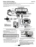
DCU

Green

Black

Yellow

PIN   

1 - 

NOT USED

2 - YELLOW

3 - GREEN

4 - 

NOT USED

5 - BLACK

6 - 

NOT USED

Please Note:

Data cable connections must 

be made using 

electrically 

straight 6 Pin 4 conductor 

modular cable

 (RJ14/6P4C)

Please Note:

Data Cables 

for Serial Control 

Provided by Others 

SP-KSM

Key Switch-

Service Position

Optional R2D7, 

RS232 Controller

RP/RQ Bus Ports

 for remote controls

such as 

IR Eye, RF Receiver, 

LED Wall Switch 

and 

RS232.

LVC-S

Show Position

Low Voltage Trigger

(6-24 VDC)

(Polarity Independent)

Function 

Indicator

To RS232 Serial Port:

Blue = Not Used

Yellow = Rx 

(Data from control system)

Green = Tx 

(Data to control system)

Red = Not Used

Black = Gnd

 (Signal Ground)

White = Not Used

DETAIL OF DATA CABLE 

SPLITTER BOARD

Scissor Lift SLX by Draper


page 5 of 8

www.draperinc.com

(765) 987-7999

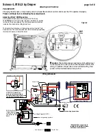
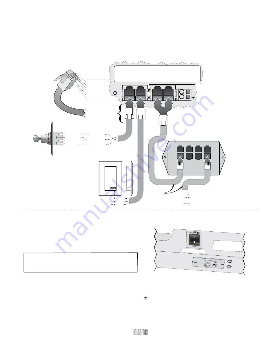
Connecting Controls to Data Cable Splitter Board 

Controls plug into the 

Data Cable Splitter Board


(See diagram below) 

which is located on the Top Frame on the front side of the lift, using 

RJ14/6P4C connectors

For IR or RF Remote Control

, use data cable with RJ14/6P4C connectors on both ends. 

For serial control of "Show" position, 

use data cable with RJ14/6P4C connectors on both ends and an R2D7 Serial Control Interface. 

Plug into the "RP/RQ" input.

Figure 7

Clearing and Resetting Show Position

CLEARING THE SHOW POSITION AT CURRENT SHOW POSITION:

1

 Move lift to the show position.

2

 While lift is at the show position press and hold the Key Up toggle 

  switch and release once the Lift begins moving upward.

3

 The show position is now cleared and ready for a new show position 

  to be set.

PROCEDURE FOR SETTING SHOW POSITION:

1

 Now that the show position has been cleared, use wall switch up and down 

  buttons to get lift into desired show position. 

2

 While lift is at desired show position, press and hold the Key Down toggle 

  switch until lift begins to move upward. Lift will begin a calibration cycle 
  where it will move upward for two seconds, stop then move down for one 
  second and then the Lift will return to the desired show position.

PLEASE NOTE: At this point the Key Switch will not operate until 

the new “Show Position” has been set. Also the 3-Button Wall Switch 

changes into a maintain, push and hold type button, for continuous 

movement. This allows for easy setting of new “Show Position”) 

Optional Delay Feature

1

 When the Optional Delay Feature is installed the Delay Switch must be in   

  the "Delay On" position for normal operation.

2

 If the Optional Delay Feature is installed and the "Show Position" requires   

  adjusting, then the "Delay Switch" must be switched to 

Off 

while adjusting  

  the show position.

 CAUTION:


Be sure all switches are in 

Off

 position before adjusting limit 

switch. Always be prepared to shut lift off manually when new adjustment is 

being tested. Please refer to wiring diagram.

PLEASE NOTE: If the Scissor Lift loses power, the 

DOWn


function will not work until you operate the lift in the 

UP 

direction using the wall switch. This allows the lift's control 

encoder to recognize it's "home" location.

NOTICE -

 Delay Feature Will

Not Operate Properly Without

The Optional Current Sensor 

Connected To The Lift.

KEEP DELAY IN OFF POSITION 

WHEN 

CURRENT SENSOR IS NO

T USED

Please Note:

Any control, including automated  

dry contact systems, being  

connected to the wall switch input 

MUST send a momentary signal.

Summary of Contents for SLX

Page 1: ...ior to installation Please Note Packaging must be removed from lift before testing 12 Follow instructions carefully Installation contrary to instructions invalidates warranty 13 Do not obstruct operation of Scissor Lift SLX with fingers or any object Serious injury or damage could result 14 Lift is intended for use with product weighing not more than 350 pounds 15 Scissor Lift SLX is designed to a...

Page 2: ...e cautious If unit fails to operate properly press STOP and recheck electrical connections before proceeding Cycle unit down and up several times to confirm satisfactory operation Caution Do not pull on or touch safety belt when unit is in motion If belt locks the cables will unspool Caution Obstructing bottom pan may cause cables to unspool Caution Do not operate Scissor Lift SL without a minimum...

Page 3: ...on of the surrounding ceiling units should be operated to confirm that optional ceiling closure panel stops just short of touching ceiling in closed position Warning Keep fingers and other objects away from automatic ceiling closure and scissor mechanisms when unit is operating Serious injury or damage could result Attaching Universal Projector Mount to Projector Pan If you ordered the unit with o...

Page 4: ...sed a motor failure may occur Installing Optional Ceiling Trim Kit The Scissor Lift SLX is available with a Ceiling Trim Kit which consists of the lower section of the Environmental Air Space Housing and the optional closure panel see Fig 6 1Install Scissor Lift SLX as previously described in these instructions 2Install bottom section of Environmental Air Space Housing and Trim Ring in opening Thi...

Page 5: ...position is now cleared and ready for a new show position to be set PROCEDURE FOR SETTING SHOW POSITION 1 Now that the show position has been cleared use wall switch up and down buttons to get lift into desired show position 2 While lift is at desired show position press and hold the Key Down toggle switch until lift begins to move upward Lift will begin a calibration cycle where it will move upwa...

Page 6: ...s located in the plastic sleeve with these instructions ROTATE TO ADJUST DOWN Limit Switch R R R R R R R ROTATE T T T T T T TO O T T A A A A A A ADJ A A A A A UST DOWN Adjusting FULLY DOWN position Limit switches for the Scissor Lift SL are preset at the factory The DOWN limit switch is set for the fully down maintenance position for the size lift you have ordered The limit switch assembly is loca...

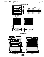
Page 7: ...921 mm 391 16 992 mm 42 1067 mm 35 889 mm 19 16 39 6875 mm 1 8 3 175 mm Top View Front View Side View 39 1 8 994mm x 39 1 8 994mm Lipless Closure Dimensions Scissor Lift SLX Dimensions Table A Closed Extended Model Height Height SLX10 141 16 10 7 SLX14 165 16 14 2 SLX17 189 16 17 8 SLX21 2013 16 21 3 SLX24 231 16 24 9 SLX28 255 16 28 5 5 20 41 48 22 19 41 Front Back View Side View ...

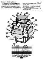
Page 8: ...28 544 02SA Frame SLX Plenum 2 1 C028 545 07SA Frame SLX Trim Ring 3 4 C044 178SA Panel SLX Plenum Side 4 4 C044 180SA Panel SLX Plenum End 5 2 C044 179SA Panel SLX Middle End 6 2 C044 177SA Panel SLX Plenum Middle Side 7 1 C095 123SA Cover SLX Plenum 8 28 C020 325 Screw 8 32 x 3 8 Type 1 HWH 9 40 C018 051 Nut 8 32 Zinc Hex KEPS 10 12 C013 070 Washer 188 I D x 5 O D x 07 TK Nylon Flat 11 24 C020 1...

Reviews: