


13
NOTE: Remove the plug from the socket before carrying
out adjustment, servicing or maintenance.
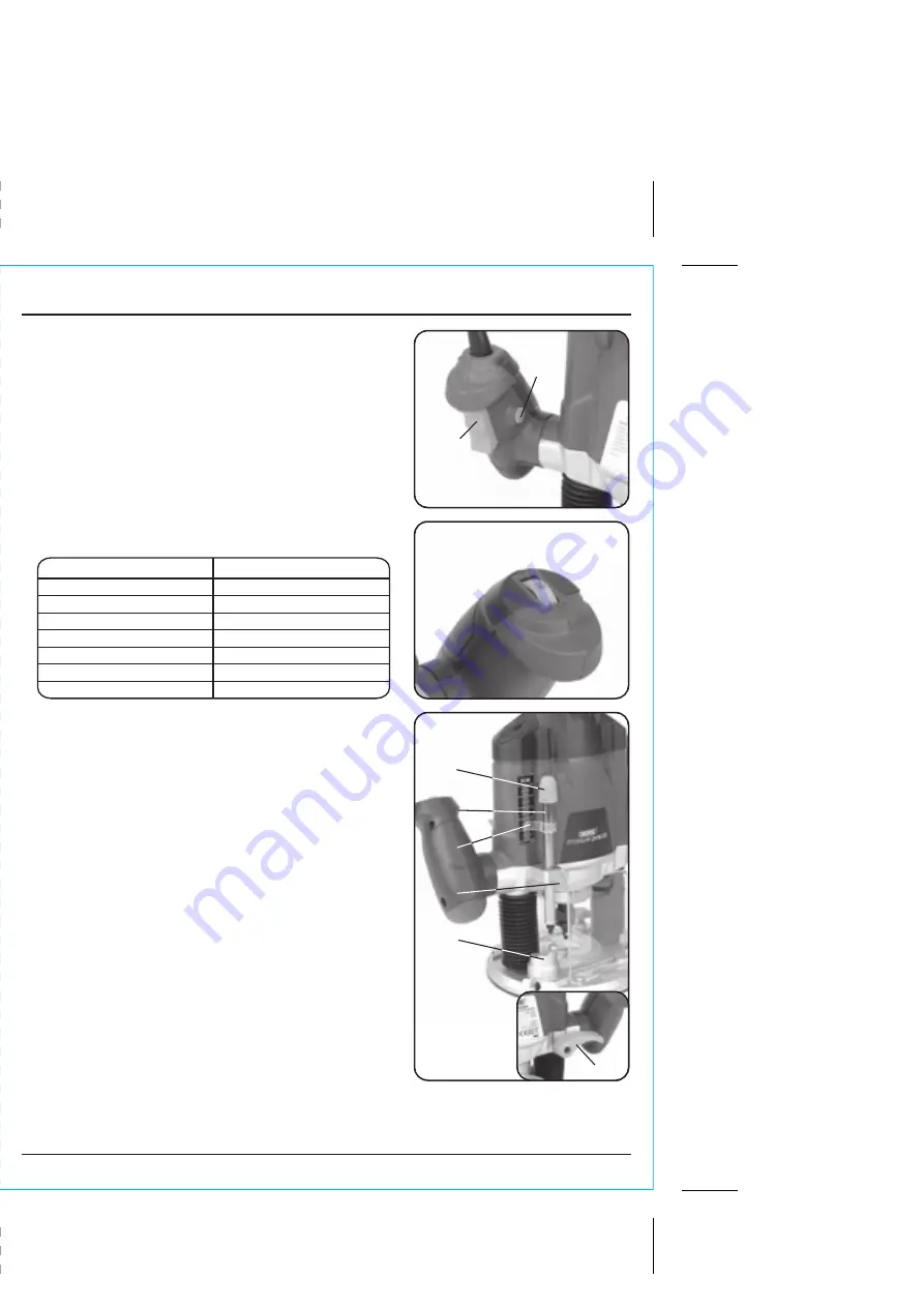
9.1 TRIGGER SWITCH - FIG. 5
The router is fitted with a safety lock off switch to
prevent accidental starting. Press and hold lock button
. Pull trigger
and the router will start.
FIG.5
NOTE: Cutting speed depends on material, cutter size,
cutting depth etc. Larger router bits will require a
slower speed. For more detailed information refer to a
routing/woodworking book.
9.3 SETTING THE CUTTING DEPTH - FIGS. 7 - 9
With a suitable router bit fitted place the router on to
the workpiece. Rotate the turret
to the lowest
position. Slowly plunge the router until the bit just
touches the workpiece. Lock the router in this position
with the plunge lock lever
.
Ensure the height adjustment lock
is not tight and
lower the rod
until it touches the turret.
If necessary turn the fine height adjustment control
to align the nearest digit on the scale against the
pointer
.
Take note of the setting before raising the rod upward
to set the plunge depth (the difference between the
two measurements) and securely tighten the height
adjustment lock
. eg. scale reads 23. After
adjustment reads 33, the plunge depth will be 10mm.
Release the plunge lock lever and raise the router back
to full height. Rotate the turret round several positions
and the router is set up ready to begin work.
FIG.7
FIG.6
9.2 VARIABLE SPEED DIAL - FIG. 6
The variable speed dial is marked 1 to 7 and correspond:
9. BASIC ROUTER OPERATIONS
SETTING
APPROX.SPEED (r/min
)
0
0
0
,
0
1
1
0
0
0
,
4
1
2
0
0
0
,
8
1
3
0
0
5
,
2
2
4
0
0
5
,
4
2
5
0
0
0
,
8
2
6
0
0
0
,
0
3
7


