5
DRAWMER
DSL424 O
PERATOR’S
M
ANUA
L
CONTROL DESCRIPTION
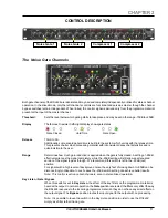
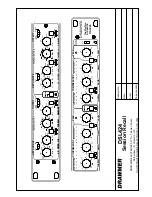
Both gate channels of the DSL424 are identical and may be used completely independently or linked for stereo channel
operation. In the linked mode, only the left channel’s controls are functional and serve as master, though the channel
bypass switches remain independent. When linked, the control signal is derived only from the programme material
present at the input of the master channel.
Threshold:
Sets the level below which gating starts to take place and may be set in the range -70dB to +20dB.
Display
The famous Drawmer traffic light display shows gate status
Gate Closed
Hold Time
Gate Open
Release
10mS to 5S.
Additionally, some envelope hold time is built into the system which varies with the release time.
This prevents chatter when processing material with inconsistent decay characteristics and is
quite invisible to the user.
Range
Determines how much gain reduction is applied when the gate is fully closed. A setting of -90dB
effectively silences the signal completely, while the -20dB setting will still allow an attenuated
version of the signal to pass through. We recommend this switch is left in the -90dB (out)
position.
For signals with a high levels of background noise, the very fact of closing down to -90dB can be
disconcertingly noticeable. In such cases the -20dB switch setting can achieve better results.
Note: This control is active on both channels, even in stereo linked operation
.
Key Listen / Gate / Bypass
When this switch is set to
Key Listen
, the effect of the key filters on the programme material is
heard at the output. In normal operation, the
Gate
position is selected; the filters only affect the way
the DSL424 responds to the incoming programme material - they do not have any direct effect on
the output signal. The
Bypass
position routes the input signal to the output with no processing.
Note: It is possible to leave the switch in the Key Listen position in order to use the DSL424
simply as a filter rather than a gate
.
The Noise Gate Channels
CHAPTER 2
Noise Gate 1
Noise Gate 2
Compressor 1
Compressor 2


