
Technical Data
MiTime T721R
Voltage
230V a.c. +10% -10% 50Hz
Switch Rating
2 (1) A 230V a.c. each switch
Ambient temp
Operating: 0º to 45ºC
Storage: -20ºC to 50ºC
Without mains
power
Display: blank
Time: always kept
Programme times: always preserved
Programming
resolution
1 minute
Wiring
Fixed wiring only, to comply with
current IEE regulations
Maintenance
Must be maintained by a qualified
electrician or heating engineer
Pollution degree
2
Rated impulse
voltage
2.5kV
Ball pressure test
temperature
75ºC
Relevant EC
Directives:
2006/95/EC Low Voltage Directive
2004/108/EC Electromagnetic
Compatibility Directive
2006/66/EC Battery Directive
2011/65/EU RoHS Directive
Applied Standards:
En60730-1; En60730-2-7
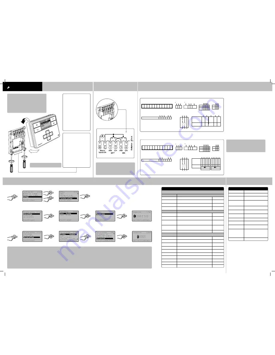
Step 2:
Wiring
→
Connect the wiring as shown below.
Step 3:
Connection Charts
Step 4:
Installer Settings
Arrowed numbers relate to the junction box.
* Consult boiler handbook for details of pump
overrun wiring.
Make the wiring connections, as shown, for the
appropriate system. For surface wiring, snap out the
cable entry strip on the bottom edge of the wall-plate.
MiTime units are double-insulated and need no earth
connection, but an earthing continuity (loop) terminal is
provided for convenience.
After wiring, plug in the unit and tighten the securing
screws. Check the mains input has a 3A fuse, and switch
on the mains.
Biflo system: Model T721R
LWC3 Junction Box
Pump
Room Thermostat
Cyl. Thermostat
Boiler
Mains Input - 230V a.c.
Motorised Valve
*Refer to Boiler Handbook for wiring details of Pump Overrun boilers. Use boiler manufacturers instructions.
Connections: The numbers printed at the tip of each arrow represent the Junction Box Terminals to which those leads or terminals should be connected.
3A
MiTime Programmer
CH
ON
HW
ON
CH
OFF
HW
OFF
L
N
4
3
2
1
2 1 NOT
USED
8 4
L N E
7 2 3
Perm.
L
N E Switch
L
7
1
2 3
DHW VALVE
CH VALVE
Function of
Leads
Drayton
22mm 2 Port Valve
28mm 2 Port Valve
Aux.SW
Motor
N
L
Bro
wn
Blue
Yell/Green
Orange
Gre
y
White
(28mm
only)
N.C
N.O
C
E
6
3
2
7 1 9
5
3
2
7 1 10
Aux.SW
Motor
N
L
Bro
wn
N.C
N.O
C
E
Blue
Yell/Green
Orange
Gr
ey
White
(28mm
only)
The white wire (28mm Valves) becomes live when the valve closes, it is not
used and is wired to 'spare' terminals for safe isolation.
1
3
2
L N E
Mains
Isolator
3 2 1 4 5
COM
CALL
SA
T.
RTS 1&2
RTS 4,6,9&10
Function
N
L 3
N L
E N L
1 3
6
8
COM
CALL
SA
T.
Drayton
HTS 3
Function
C 1 2
1
L
2
N
3
E
4
5
6
7
8
9
10 11 12
Twinzone system: Model T721R
→
INSTALLATION
Guide
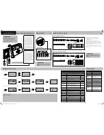
Step 1:
Mounting the Wall-plate
!
IMPORTANT:
Installation must only be carried out by a
qualified electrician or heating engineer.
Make sure mains input has a 3 amp fuse.
!
CAUTION! Before installation, make sure the
mains supply is switched off!
MiTime
Option 2: Using an existing
wall-plate
Loosen the securing screws
on the old programmer and
unplug it. Check that there is
70mm clearance to the right of
the wall-plate and 25mm above
it. Check the wiring diagram for
your product model to compare
terminals and, if necessary,
change the wiring of the wall-
plate to suit. now plug the MiTime
unit into the wall-plate and tighten
the securing screws.
Check the 3A fuse, and switch on
the mains.
Option 1: Fitting a new wall-plate
The ideal location is 1.2m above
floor level, with reasonable
lighting, good access, no
condensation, no extremes of
temperature and a supporting
surface that fully covers the
back of the unit. Position with
70mm clearance to the right,
25mm above and sufficient room
to access the securing screws
underneath. Fix, with terminals
at the top, either direct to a flat
wall using wall plugs and no. 6 x
1” (25mm) woodscrews, or on a
flush mounting single conduit box
type UA1 (BS4662) using M3.5 x
14 bolts.
!
DO NOT use a surface mounting box
→
Feature:
Description:
Factory Pre-Set:
Installer Settings
!
CAUTION!
These settings should only be modified by a qualified
person. They can influence safety and the proper functioning of the system.
Zone Settings
Customise the MiTime according to personal requirements
Select zone
Select a zone for the following actions
Rename zone
To rename an existing zone
Heating,
H Water
Delete zone
To delete an existing zone. The last zone cannot be
deleted
Min. 1 Zone
Add Zone
Add a new zone, apply a name & bind a thermostat.
A time table can be applied.
Max. 2 Zones
System Settings
These are the settings which will be applied to the MiTime unit
View product
information
View the product details, e.g. Part number, Firmware
revision etc.
Backlight settings
Available options are: On with timeout, Always On,
Always Off
On with
timeout
Screen lock
Enable or disable the lock in the MiTime unit
To Lock: Enter a 3 digit code for protection
To Unlock: Enter the 3 digit code
000
Master Code 401
Powersave
To reduce power use when not being adjusted.
Available options are: Powersave off, partial display
with key data, no display until button press
Powersave off
System Reset
Will reset all settings to factory pre-sets
Service Settings
To help comply with regulation 36 of the Gas safety [Installation & Use]
regulations 1998
Si Status
Enable or disable Service mode
Disabled
Si Type
Select between, Reduced Comfort, Switched Off &
no Effect (warnings only)
Reduced
Comfort
Reduced comfort
duration
Set the duration for the reduced comfort setting (0
to 60mins.)
15 min.
Si due date
Set the date the next boiler service is due
Today
Warning start
Set the number of days for the on-screen service due
warning (0 to 60 days)
30 days
Boost status
Enable or disable Service Boost
Disabled
no. of boosts
Set the number of Boosts to be available after service
is due (1 to 99)
10
Audible Alarm
Enable or disable Service Alarm
Enabled
Installer tel
Enter the Installer telephone number if required
Set password
Set password to restrict access to the Service settings
0000
From the Home screen, select
Settings
, then
Installer settings
as shown.
From here you can edit the assigned zones, rename them if required and adjust the Service settings.
If using the Service feature, remember to set the
Password
when complete.
!
IMPORTANT:
Always switch off the mains before removing
the MiTime programmer – and never fit it to a live
wall-plate!
→
LWC3 Junction Box
Pump
Room Thermostat
Cyl. Thermostat
Boiler
Mains Input - 230V a.c.
Motorised Valve
*Refer to Boiler Handbook for wiring details of Pump Overrun boilers. Use boiler manufacturers instructions.
Connections: The numbers printed at the tip of each arrow represent the Junction Box Terminals to which those leads or terminals should be connected.
3A
L N E
7 2 3
Perm.
L
N E Switch
L
7
1
2 3
1
3
2
L N E
Mains
Isolator
3 2 1 4 5
COM
CALL
SA
T.
RTS 1&2
RTS 4,6,9&10
Function
N
L 3
N L
E N L
1 3
7 8
6
COM
CALL
SA
T.
Drayton
HTS 3
Function
C 1 2
1
L
2
N
3
E
4
5
6
7
8
9
10 11 12
MiTime Programmer
CH
ON
HW
ON
CH
OFF
HW
OFF
L
N
4
3
2
1
2 1 8 NOT
USED
6 4
Function
Drayton
22mm 3 Port Mid Position Valve
28mm 3 Port Mid Position Valve
White
Gre
y
Orange
Blue
Yello
w/Green
CH
On
HW
Off
Boiler
Live &
HW On
N
E
2
5
3
8
7
!
IMPORTANT:
Always switch off the mains before removing
the MiTime programmer – and never fit it to a live
wall-plate!
Internal Wiring
→
→
→
→
→
→
→
→
→
→
✎
Installer Notes:
6444 Invensys MiSeries 2 Channel 06490187001 IssE.indd 2
27/09/2013 09:09


