background image

“INFINITY-Z” Rev.2 Ver.4     08/2013 

6


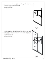
4.


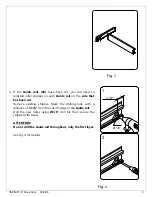
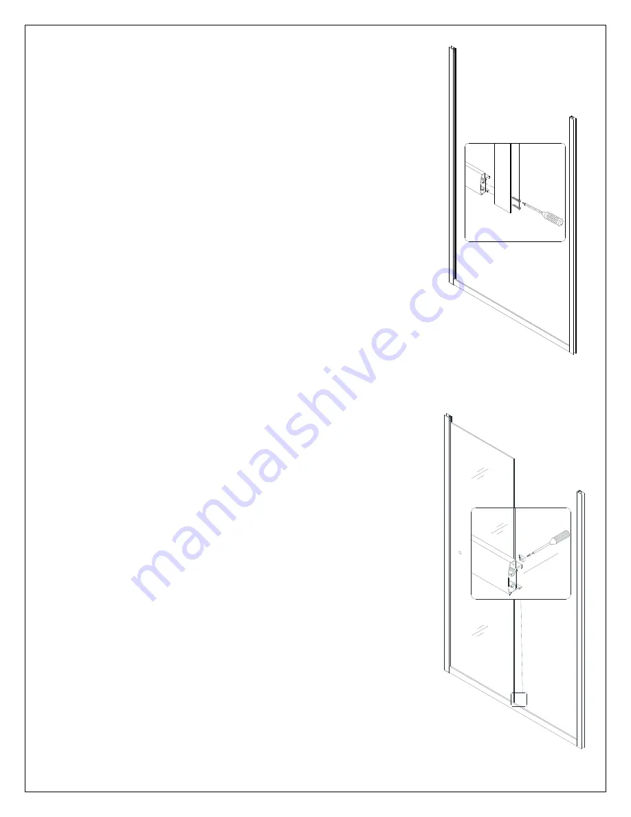
Secure the bottom 

Guide rail (03) 

to the 

Glass profiles (01)

 with 

the 

Round head screws ST4.2x25 (10)


See Fig. 5 for details. 


Fig

. 5 


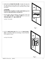
5.


Slide the

 Stationary glass (05)

 fully into the groove of the 

Glass 

profile (01)

, and then secure it to the bottom 

Guide rail (03) 

with 

the 

Glass holder (16).


See Fig. 6 for details. 


Fig

. 6 

Summary of Contents for INFINITY-Z

Page 1: ...refer to the support BathAuthority com web page Please read these instructions carefully before installing If you have any questions regarding installation please call our technical support specialis...

Page 2: ...nstalled in a new construction install all of the required plumbing and drainage before installing the shower Use a competent and licensed if required by local code plumber for all plumbing installati...

Page 3: ...5 Seal gasket 1pc 07 Anti water strip 3pcs 16 Glass holder 2pcs 08 Single side strip 1pc 17 Wheel assembly 2pais 09 Round head screw ST4 2 30 8pcs 18 Towel bar 1pc NOTE Unpack your unit carefully and...

Page 4: ...e size of your Shower model it is unnecessary to cut the Guide rails and you can continue to Step 3 If W width of your wall to wall opening is less than the size of your Shower model you will need to...

Page 5: ...rail on the side that has been cut Remove existing stopper Mark the drilling hole with a distance of 3 1 8 from the cut off edge of the Guide rail Drill the new holes using 1 8 drill bit then secure t...

Page 6: ...o the Glass profiles 01 with the Round head screws ST4 2x25 10 See Fig 5 for details Fig 5 5 Slide the Stationary glass 05 fully into the groove of the Glass profile 01 and then secure it to the botto...

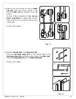
Page 7: ...not use the screwdriver or other metal objects you can scratch or damage the glass and aluminum 7 Repeat Step 3 Step 4 Step 5 and Step 6 to fasten the upper Guide rail 03 to the Glass profile and secu...

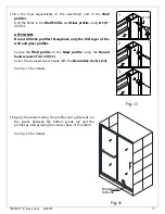
Page 8: ...in the vertical position See Fig 9 for details Fig 9 10 Using help to hold this assembly in the right position mark the drill holes on the wall through the holes on the flange of the Wall Profile Gent...

Page 9: ...einstalled If not please refer to Fig 12 for detailed installation 12 Fasten the top and the bottom Wheel assemblies 17 to the Glass door 04 The top wheels can adjust the door level with the adjustabl...

Page 10: ...do not use power screwdriver to adjust upper wheels make sure they move smoothly and the door closes tight See Fig 13 for details Fig 13 14 Install the Handle 06 to the Glass door 04 Press the anti wa...

Page 11: ...rst layer of the wall and glass profiles Secure the Wall profile to the Glass profile using the Round head screws ST4 2 10 11 Cover the exposed screw heads with the Decorative covers 13 See Fig 15 for...

Page 12: ...p Never use abrasive cleaners and cleaning products that contain scouring agents as this may scratch the surface Never use bristle brushes or abrasive sponges To ensure a long lasting hardware finish...

Page 13: ...not recommended for chrome or similar finish glass or acrylic will void the warranty For additional product maintenance instructions please refer to product installation manual DreamLine is not respo...

Page 14: ...TEL 866 731 2244 FAX 866 227 1533 WWW BATHAUTHORITY COM For more information on DreamLineTM Shower Doors Tub Doors please visit www BathAuthority com...

Reviews: