background image

© DreamLine

®

 All Rights Reserved

© DreamLine

®

 All Rights Reserved

Table of Contents

Section Title

Page #

ClearMax

®

 Coating Information

Warnings and General Preparation

2

Model Specific Preparation

3

Tools

4

Detailed Diagram of Shower/Tub Door Components

5-6

Parts List

7

Model Diagram

8

Installation Steps: LINEA Single Panel Installation

9-21

LINEA Single Panel with Towel Bar Assembly Installation

22

LINEA Shower Screens: Two Individual Panels Installation

23

LINEA Shower Screens: Two Adjacent Panels Installation

24-31

90° Degree Top Corner Bracket Installation 

(*exclusive to Two Adjacent Panel Installation)

30

Product Maintenance

32

Troubleshooting

33

Factory Parts Information

34-37

LINEA Shower Panel Installation Manual Ver 2 082021

©2021 DreamLine® All Rights Reserved.


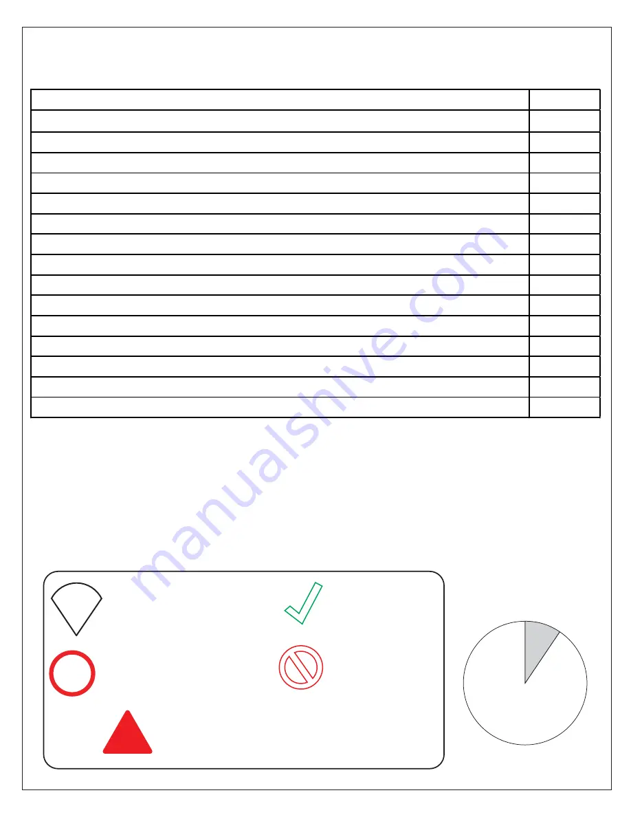
Symbol Legend

TIP

TIP 

- for ease of installation.

NOTE

NOTE 

- take note of special 

feature; additional information.

INCORRECT

 - 

not recommended.

CORRECT

 - 

recommended.

!

REQUIRED 

- requires special attention; 

signifies a warning.

Average Installation Time

1 hr

Summary of Contents for LINEA SDLI30W720XTX Series

Page 1: ...r to the model s web page on DreamLine com for the latest technical drawings installation manuals warranty information or additional product details LINEA SHDR 3230721 SHDR 3234721 LINEA w Towel Bar S...

Page 2: ...te that depending on the model the glass may be coated on either one or both surfaces For best results squeegee the glass after each use and dry with a soft cloth Installation Date OD Number optional...

Page 3: ...wer Screens Two Individual Panels Installation 23 LINEA Shower Screens Two Adjacent Panels Installation 24 31 90 Degree Top Corner Bracket Installation exclusive to Two Adjacent Panel Installation 30...

Page 4: ...ntroduction carefully Check that all the items are included in the package by marking off the components on the Detailed Diagram of Product Components page Examine all boxes and packages for shipping...

Page 5: ...n example throughout this manual For the left hand panel installation simply begin on the opposite wall and reverse the orientation of the steps shown TIP single panel installation also applies to Lin...

Page 6: ...to the bottom of the box If any parts are damaged or missing please contact DreamLine for replacement The shipping boxes may contain extra parts not used in your model configuration Retain these insta...

Page 7: ...s Two Individual Panels SHDR 3230302 SHDR 3230342 SHDR 3234302 SHDR 3234342 LINEA SHDR 3230721 SHDR 3234721 LINEA Shower Panel Installation Manual Ver 2 082021 5 2021 DreamLine All Rights Reserved rig...

Page 8: ...Adjacent Panels SHDR 3230303 SHDR 3230343 SHDR 3234303 SHDR 3234343 LINEA with Towel Bar SDLI30W720XTX SDLI34W720XTX LINEA Shower Panel Installation Manual Ver 2 082021 6 2021 DreamLine All Rights Res...

Page 9: ...l Anchor ST4 2 40mm Countersunk Screw Bottom U Channel Vertical U Channel Panel Glass 23 29 13 30 09 11 x1 x8 x1 x8 x1 x1 PVC Glass Spacer 0 5mm 90 Degree Top Corner Bracket 34 x1 Towel Bar 05 x1 NOTE...

Page 10: ...nstall this 34 72 863 6 1828 8mm single panel into a finished opening no less than 56 1422 4mm that will allow for at least 22 558 8mm of unobstructed access into the shower area NOTE When installing...

Page 11: ...ertical U Channel 09 allows for up to 1 2 12 7mm of out of plumb adjustment verify the walls and threshold with a level before proceeding with the installation 1 2 Max wall surface glass edge 0 0 0 0...

Page 12: ...ts Reserved Tools Needed Parts Needed 10 LINEA Shower Panel Installation Manual Ver 2 082021 2021 DreamLine All Rights Reserved W H Fig 2 Panel Glass Height H 11 x1 Panel Glass Width W 3 16 4 78mm Add...

Page 13: ...s onto the Panel Glass and place into the finished opening Mark the Bottom U Channel where the glass edge is and proceed to trim The maximum out of plumb adjustment is 1 2 12 7mm wall is out of plumb...

Page 14: ...All Rights Reserved Tools Needed 12 LINEA Shower Panel Installation Manual Ver 2 082021 2021 DreamLine All Rights Reserved TIP Mark at least three 3 holes for the Bottom U Channel 29 Fig 4 right wall...

Page 15: ...ld surfaces use the appropriate drill bit for the type of surface material 2 1 3 NOTE For installation into an Acrylic Threshold drill an 1 8 3mm hole and use the ST4 2 x 40mm Countersunk Screw 23 OR...

Page 16: ...d 14 LINEA Shower Panel Installation Manual Ver 2 082021 2021 DreamLine All Rights Reserved To prevent damage to the glass Fully countersink the screws so the screw heads do not stick up above the sur...

Page 17: ...Parts Needed 15 LINEA Shower Panel Installation Manual Ver 2 082021 2021 DreamLine All Rights Reserved 2 50 8mm Fig 7a Fig 7b Cut several 2 3 50 4mm 76 2mm pieces of the PVC Glass Spacer 0 5mm 34 DO N...

Page 18: ...erved Fig 9 right wall single panel installation shown Fig 8 NOTE The Vertical 09 U Channel sits on top of the Bottom 29 U Channel right wall single panel installation shown 1 2 MAX 2 3 1 For the sing...

Page 19: ...the wall drill a 3 16 4 76mm hole up to the stud drill an 1 8 3mm pilot hole into the stud and use the ST4 2 x 40mm Countersunk Screws 23 OR If no stud is present behind the wall drill a 5 16 8mm hole...

Page 20: ...Manual Ver 2 082021 2021 DreamLine All Rights Reserved 23 x8 2 3 Fig 11 To prevent damage to the glass Fully countersink the screws so the screw heads do not stick out from the surface of the U Chann...

Page 21: ...llation Manual Ver 2 082021 2021 DreamLine All Rights Reserved 1 2 3 After applying silicone into the Bottom U Channel install several 2 3 pieces of the PVC Glass Spacer 0 5mm 34 into the Bottom U Cha...

Page 22: ...Manual Ver 2 082021 2021 DreamLine All Rights Reserved 1 2 Fig 13 1 2 1 2 NOTE Slide the panel glass into the Vertical U Channel 09 first and then slide it down into the Bottom U Channel 29 right wal...

Page 23: ...d to be clean and free of debris before applying silicone Allow 24 hours for the silicone to cure before using the shower Fig 14 24 Hours right wall single panel installation shown This completes the...

Page 24: ...single panel with Towel Bar Assembly 05 Install the Towel Bar Assembly 05 ensuring all vinyl gaskets are present to prevent glass to metal contact as shown in Fig 15b After the installation of the to...

Page 25: ...n shown Fig 16c Fig 16b Return Panel Inline Panel The installation of these two panels are identical to the single panel installation Follow Steps 1 through 14 to install each panel separately Centeri...

Page 26: ...and threshold to determine where to install the panels as shown in Fig 17b NOTE This model is fully reversible The installation is shown with the return panel to the right in Fig 17a For installation...

Page 27: ...lation Manual Ver 2 082021 2021 DreamLine All Rights Reserved TIP Use a carpenter s square for accuracy when marking the threshold Return Panel Glass Width W 3 16 4 78mm Return Panel Glass Height H H...

Page 28: ...r 1 2 NOTE All 45 cuts are referenced from the outside dimension miter cut for right hand return panel installation shown or or or 29 x1 or Glass Width W 1 16 1 6mm L Cut the Inline Panel Bottom U Cha...

Page 29: ...nnel 09 Fig 22a Fig 22b 29 09 x1 x1 NOTE Use at least four 4 screws to attach the Vertical U Channel 09 and three 3 to attach the Bottom U Channel 29 2 51mm Fig 23a Fig 23b As demonstrated in Fig 23b...

Page 30: ...drill a 5 16 7mm hole and insert the Wall Anchors 08 and use the ST4 2 x 40mm Countersunk Screws 23 For installation into an Acrylic Threshold drill a 1 8 3mm hole and use the ST4 2 x 40mm Countersunk...

Page 31: ...panel glass Do Not Exceed 1 4 6mm of vertical adjustment Return Panel Glass must match the installed other panel glass at the standard model height of 72 1829mm TIP 11 x1 After applying silicone into...

Page 32: ...ical adjustment Return Panel Glass must match the installed other panel glass at the standard model height of 72 1829mm TIP 11 x1 Fig 28 inline panel inline panel return panel return panel inline pane...

Page 33: ...Rights Reserved TIP Apply a bead of 100 silicone on the inside corner of the shower where the two glass panels intersect inside 100 silicone 24 Hours NOTE The surfaces need to be clean and free of deb...

Page 34: ...istle brushes or abrasive sponges that may scratch the surface of the glass HARDWARE To ensure a long lasting finish wipe off all metal parts after each use with a soft cloth Do not use abrasive clean...

Page 35: ...red to the threshold Inspect the silicone caulk and ensure that a complete application of silicone caulk has been applied Allow 24 hours to cure the silicone before attempting to use the shower LINEA...

Page 36: ...rsunk Screw 9 pcs 29 04154011 0914 04154041 0914 04154061 0914 04154091 0914 U Channel 1 Aluminum for 10mm 3 8in Glass 1 pc 34 07550083 PVC Glass Spacer 0 5mm 1 pc ITEM FACTORY PART NUMBER ITEM DESCRI...

Page 37: ...1 1118 04154041 1118 04154061 1118 04154091 1118 U Channel 1 Aluminum for 10mm 3 8in Glass 1 pc 34 07550083 PVC Glass Spacer 0 5mm 1 pc ITEM FACTORY PART NUMBER ITEM DESCRIPTION QTY 05 07231012 072340...

Page 38: ...minum for 10mm 3 8in Glass 1 pc 34 07550083 PVC Glass Spacer 0 5mm 1 pc SHDR 3230302 ITEM FACTORY PART NUMBER ITEM DESCRIPTION QTY 11 010137109 30 in 757mm Stationary Panel Glass 2 pcs SHDR 3230342 IT...

Page 39: ...Glass 1 pc 30 07011101 90 Degree Top Corner Bracket 1 pc 34 07550083 PVC Glass Spacer 0 5mm 1 pc ITEM FACTORY PART NUMBER ITEM DESCRIPTION QTY 11 010137109 30 in 757mm Stationary Panel Glass 2 pcs ITE...

Page 40: ...ights Reserved DreamLine All Rights Reserved TEL 866 731 2244 FAX 866 857 3638 DREAMLINE COM For more information on DreamLine Shower Doors and Enclosures please visit DreamLine com 2021 DreamLine All...

Reviews: