Rev. 1.2.
5
Cabin Installation
1.
Choose the location where you will be installing the tray, mark the location of the tray
because you may need to move it out from the position for better assembling
procedure. Check on the drain if it is fastened tight enough to make sure it won’t leak
after complete tray installation.
2.
Also check all the hose connections to prevent leakage. Your plumber may want to
replace the drain flex hose to hard PVC pipes which is also possible (instructions are
provided in the manual).
3.
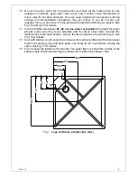
For installation of the drain in the floor please refer to the Legs and frame position
(top view) diagram and fig1 (actual poison of the drain and frame on the tray).
4.
Install the water outlet and power supply box. You need 1/2” minimum water supply
lines for hot and cold water with shout off valves.
Power supply is required 20A
220V dedicated #12 3/1 wire line with GFCI breaker.
5. Place
the
Tray (5)
in the required position. Adjust the legs to level the tray in case
the surface is uneven. Fasten the counter nuts on the legs to secure the height. See
Fig 2 for details.
NOTE: For steps 6, 7 and 8, it will be necessary to apply silicone sealant
between the panels and the panels and tray.
6. Move
the
Tray (5)
out; put the
Control panel (1)
onto the tray; then secure them
with
Round head screws ST4.2×25 (12)
. See Fig 3 for details.
7. Locate
the
Left stationary glass (2)
onto the tray. Secure the left stationary glass
and the control panel with
Bolt M4×16 (9)
. Secure the tray and the left stationary
glass with
Round head screws ST4.2×25 (12)
. See Fig 4 for details.
8.
Repeat Step 7 to install the
Right stationary glass (3)
. Attach the
Glass bracket
(13)
to the left stationary glass and the
Hand shower bracket (14)
to right stationary
glass. See Fig 5 for details.
9.
Locate the stationary glass panels from the package. Secure the
Connectors (8)
and the guide rail of the
Stationary glasses (6)
with
Round head screws ST4.2×10
(10)
. See Fig 6 for details.
10. Put
two
Wheel assemblies (20)
into the groove of the upper guide rail; then locate
the
Glass door (07)
to the position. Secure it using
Bolt M5×8 (21)
. See Fig 7 for
details.
11. Put the shower enclosure assembly onto the tray. Drill holes on the glass profiles of
the stationary glass; then secure them with
Round head screws ST4.2×16 (11)
.
See Fig 8 and Fig 9 for details.
12. Apply the silicon sealant on the top aluminum profiles of the control panel
(1)
, left
and right stationary panels
(2,3)
and stationary glass
(6)
. Put the
Roof (4)
on the top
of the shower enclosure assembly. Secure the roof and the right and left stationary
glass with
Round head screws ST4.2×25 (12)
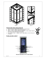
. See Fig 10 and Fig 11 for details.
13. Install
the
Glass shelf (15)
and the
Guardrail (16)
onto the left stationary glass. See
Fig 12 for details.
14. Place
the
Generator assembly (17)
on the tray; then secure it to the tray with Bolt
M6×25 (with washer) (22)
. Connect the light, fan, speaker wire from the roof to the
generator. Connect the steam generator circuits; then connect it to the power supply.
See Fig 13 for details.
DO NOT turn power supply on until the water supply, the
drain and steam line will be connected.
15. Connect the flexible hose to the shower head. Secure this item in place on the back
panel. Make sure all the water connections are water tight. Put the drain pipe into
the drain opening in the floor. Connect hot water to the red mark water inlet and cold
water to the blue mark water inlet.


