10 |Dresser Natural Gas Solutions
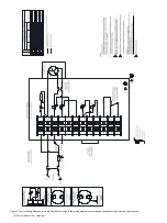
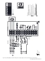
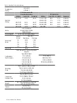
Figure 3 - Typical Wiring Diagram for Single Phase, Please refer to the wiring diagram came with your units before you work on the actuators.
1.
2.
DO NOT PERFORM HI-POT TEST ON TERMINAL BLOCK LOCATIONS 10, 11, & 12.
CUSTOMER ALTERNATIVE
FOR OPTIONAL DRY CONTACTS
DETAIL A
1
2
3
4
CAPACITOR CONNECTIONS
WITH OPTIONAL SERIES
WIRE RESISTOR
DETAIL C
STANDARD CAPACITOR
CONNECTIONS
DETAIL B
LEGEND
E
E
7
7
4
3
3

