Instruction ES2007 4/98
Models 4700P and 4700E
18
Calibration
Warning: Before commencing any calibration or
maintenance procedure on these positioners, en-
sure that the valves under control are isolated
from the controlled process and that the area is
verified as nonhazardous.
General
The Model 4700P and 4700E positioner, when factory
mounted, has been calibrated for the proper valve, valve
action, and positioner action. If, for any reason, the cam
holder (36) setting has been disturbed (i.e., a change of
positioner action, field mounting, maintenance, etc.), it is
necessary to follow all steps of the calibration instructions,
according to desired actuator action and positioner action.
Calibration may entail just a simple adjustment or a com-
plete field mount. Define the scope of work and follow the
applicable sections.
Caution: Do not attempt to remove cam if cam is
not at low signal line of lobe (low end of range).
Refer to calibration instruction for proper valve
action and positioner action before removing or
replacing cam and tightening set screws (35) to
proper torque.
Zero Adjustment (Figure 19 & 20)
The zero adjustment is made with the zero nut (4B). When
the positioner is installed and the pneumatic circuits are
connected apply low instrument signal (i.e., 3 psi for 4700P,
4 mA for 4700E), release locknut (4C) and turn zero nut (4B)
to adjust valve plug to proper position (open or closed). Then
tighten zero lock nut (4C).
Note: Do not attempt to adjust zero nut with signal
above low end of signal range. If valve is seated at low
Mounting Cam Coupling
(Figure 19 & 20)
The cam coupling (34), used on rotary actuators, is posi-
tioned on the shaft with the key engaged in the shaft slot
and the set screws (35) to the top and side. The coupling
hold-down screw (32) with the lockwasher (33) is torqued
to 125 inch-lbs.
Mounting Cam
The cam holder (36) and cam (26) are positioned on the
cam coupling (34) so that the desired cam lobe’s low signal
line is properly adjusted on the cam follower (4A). Proper
adjustment is achieved when:
1. The desired cam lobe’s low signal line is in alignment with
the “raised reference line” on the positioner (Figure 19).
2. The cam is centered between the two arms of the cam
lever S/A (3) (Figure 19).
Changing Lever S/A Orientation
(see pages 27 - 29)
If lever S/A (3) must be changed, remove screw (28)
and washer (27), and cam (26) from cam shaft. Remove
retaining ring (17) and flat washer (16). Remove lever S/A
(3) from pivot post. Lift and rotate lever S/A (3) on spring
end 180
°
to desired position. (Do not rotate spring end;
socket head screw on spring must face outward.) Replace
flat washer (16) and retaining ring (17) on pivot post.
Lever S/A Orientation (see pages 27 - 29)
The relative position of the lever S/A (3) for a selected cam
lobe must be correct. The lever S/A can be mounted with its
pivot post to the left or right of the cam center.
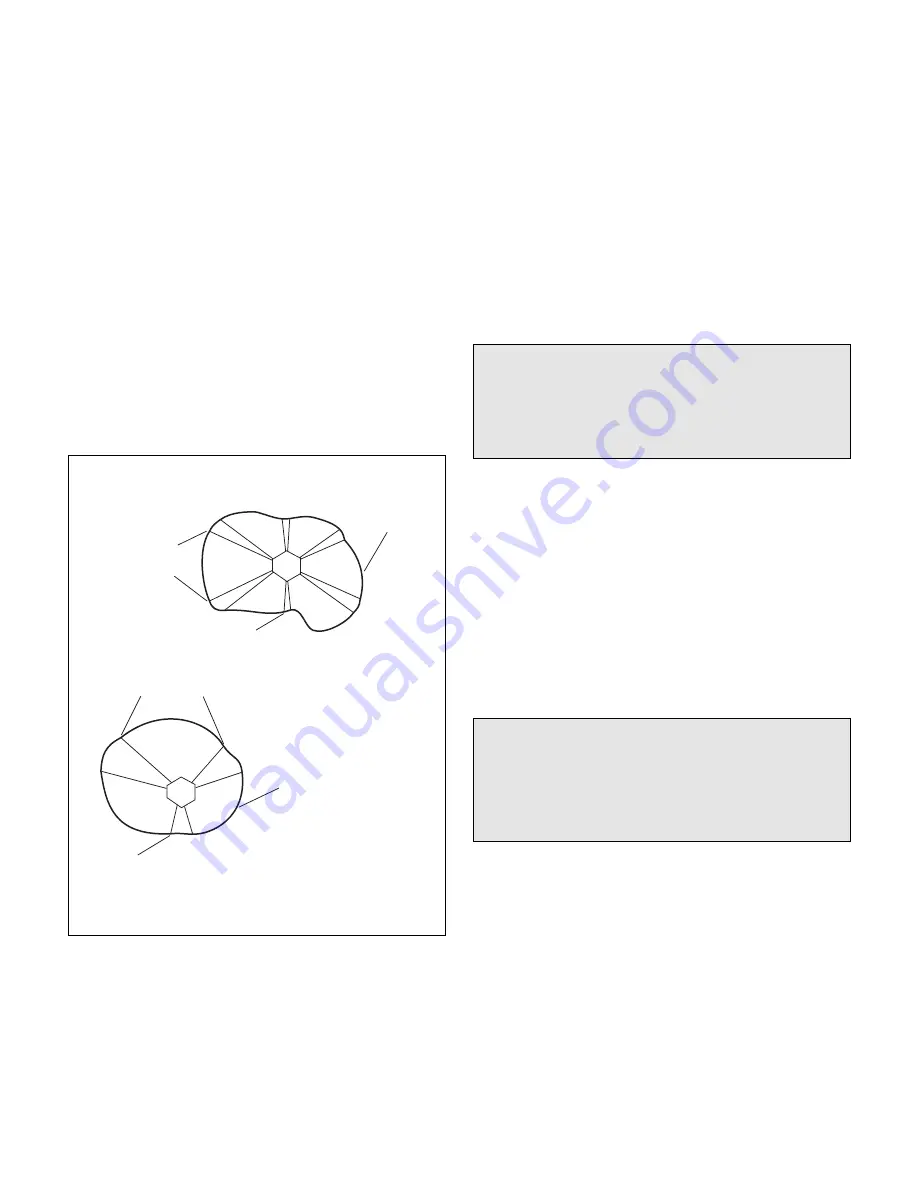
Lobe Identification
Figure 17
1
2
3
4
5
6
Lobe
(Lobe 3)
Low Signal Line
(Lobe 1)
Low Signal Line
(Lobe 1)
Lobe
(Lobe 3)
Lobe Lines
(Lobe 6)
Lobe Lines
(Lobe 2)
90
°
1
2
3
Note: The low signal line is the shortest
lobe line defining a particular lobe.
Summary of Contents for Masoneilan 4700E
Page 15: ...15 Instruction ES2007 4 98 Models 4700P and 4700E Figure 14 FM Installation ...
Page 16: ...Instruction ES2007 4 98 Models 4700P and 4700E 16 Figure 15 CSA Installation ...
Page 17: ...17 Instruction ES2007 4 98 Models 4700P and 4700E Figure 16 CENELEC Installation ...
Page 32: ...Instruction ES2007 4 98 Models 4700P and 4700E 32 Figure 20 4700E Rotary Reciprocating ...


