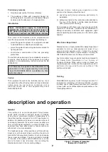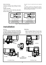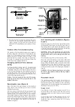
The supply connection of the air filter-regulator model
77-4 is 1/4” NPT. Adjust the output pressure of the air
filter-regulator to the pressure indicated on the serial
plate of the actuator. Admissible maximum pressures on
the positioner are in accordance with the valve and the
actuator on which it is mounted. For Camflex II valves
these maximum pressures are indicated in the
Instruction No EF 50004 E. For Varimax valves, they are
indicated in Instruction No EN 3000 E
Output circuit
The pneumatic output connection to the actuator should
be particularly tight.
Electrical circuit
See Instruction sheet No ES 50004-000 E.
General
1.
The Model 8013 Positioner, when factory mounted,
has been calibrated for the proper valve and
positioner actions. If for any reason the cam and
cam bushing (159) setting has been destroyed (for
example, a change of positioner action or cam lobe,
for field installation or for maintenance, etc...) then it
is necessary to follow all steps of calibration
instructions, according to the desired actuator and
positioner actions.
2.
Connect air lines to positioner and actuator. Connect
the leads of the input electric signal respecting
polarities stamped on the terminal board.
3.
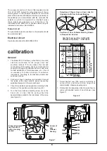
Check force balance spring position according to the
direction of the positioner action (see Figure 5)
4.
Turn the force balance adjusting screw (6) on the
beam (41) in order that the spring should be
approximately parallel to the joint plane of the case.
(see Figure 5).
6
calibration
3
4
5
6
1
2
MasoneilanMasoneilan
160
156
155
151
158
159
155
160
5
Center of
cam
follower
bearing
Figure 7
Proper alignment
line for Lobe 5
with valve plug
seated
3
4
5
6
1
2
,
,
,,
,
12
11
10
9
8
7
Figure 6
,,
,,
,,
,,
Masoneilan
Masoneilan
11
1
4
3
11
1
4
3
5
2
10
9
5
2
10
9
0-100 % LIN.
0-100 % PERC.
0-50 % LIN.
50-100 % LIN.
0-100 % LIN.
0-100 % PERC.
0-50 % LIN.
50-100 % LIN.
0-100 % LIN.
0-100 % PERC.
0-50 % LIN.
50-100 % LIN.
0-100 % LIN.
0-100 % PERC.
0-50 % LIN.
50-100 % LIN.
DIRECTE
•
DIRECT
FERMANT
PAR
MANQUE
D’AIR
•
AIR
TO
OPEN
OUVRANT
PAR
MANQUE
D’AIR
•
AIR
TO
CLOSE
INVERSE
•
REVERSE
DIRECTE
•
DIRECT
INVERSE
•
REVERSE
• SECTEUR
CAME
• CAM
LOBE
• ÉCHELLE &
CARACT.
• RANGE &
CHARACT.
• ACTION
POSITIONNEUR
• POSITIONER
ACTION
POSITIONNEUR SÉRIE 8013
8013 SERIE POSITIONER
• ACTION
VANNE
• VALVE
ACTION
18-54146
MADE IN FRANCE
• POUR CHANGER L’ACTION DU POSITIONNEUR SE
RÉFERER À LA NOTICE D’INSTRUCTIONS
• REFER TO INSTRUCTION MANUAL FOR CHANGING
POSITIONER ACTION
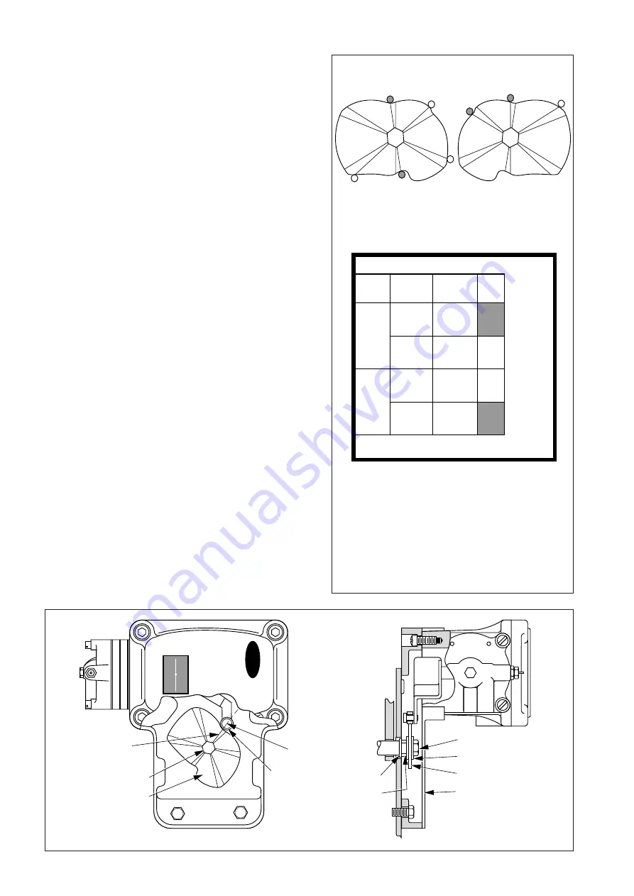
Selection of Proper Line on Cam Lobe for
Alignment with Cam Follower Bearing
Position of Cam Follower Bearing Shown
in Respect to Lobe line
Camflex II cam part No: 041126-181
Varimax cam part No : 4001 10353
1.
Select desired cam lobe number, according to
valve action, positioner action, range and
characteristic. Observe shading code.
2.
Rotate cam to align proper lobe line (as shown in
code) with shaded center of cam follower. (see
Figure 7).


