Alarm Status
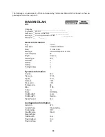
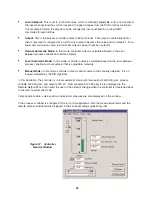
There is a Module Status box in the top right of Controller Monitor window. This box displays the status
of the process variable alarms. The alarms may be absolute or deviation alarms and are configured in
Controller Parameters window:
•
Absolute alarms: If the process variable is below the low alarm limit or above the high alarm limit,
the alarm light is turned on.
•
Deviation alarms: If the difference between the setpoint and the process variable is below the low
alarm limit or above high alarm limit, the alarm light is turned on.
Changes of Setpoint and Output of Process Controller
In manual mode, controller output is set to its previous value at transfer. The O button is enabled in
manual mode. The output value can be changed by one of the following methods:
•
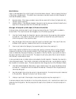
Click the O button beside the Output box, type an output value in the popup Input Data window
and click OK. The output is set and the valve should move toward the new position setpoint,
which corresponds to new controller output.
•
Drag the triangle in the horizontal (output) bar graph to a desired output. The output to be set is
indicated in the output box. Release the mouse to set the new output.
•
Click on each side of the triangle in the output bar graph moves the output by 5%.
If the S button beside the Set Point box is enabled, the previous controller mode is in local automatic.
Otherwise, the previous mode is remote automatic. The local setpoint value can be changed if the S
button is enabled and the setpoint tracking is not selected. Click the S button, type a setpoint value in
the popup Input Data window and click OK. The setpoint is set and is used at the moment of transfer
from manual to local automatic mode.
In local automatic mode, controller output is calculated by the PID algorithm. Therefore, the output can
not be changed manually. The O button is disabled in local automatic mode. Local setpoint is used for
the calculation of controller output. The local setpoint can be changed by one of the following methods:
•
Click the S button beside the Setpoint box, type a setpoint value in the popup Input Data window
and click OK. The setpoint is set and indicated numerically in the setpoint box and graphically in
the vertical bar graph.
•
Drag the triangle in the vertical bar graph to a desired setpoint. The setpoint to be set is indicated
in the output box. Release the mouse to set the new output.
•
Clicking on each side of the triangle in the vertical bar graph moves the setpoint by 5%.
In remote automatic mode, the setpoint is from the primary channel (+ and - terminals) and output is cal-
culated by the PID algorithm. Both the setpoint and output of the controller can not be manually set in
this mode.
94

