background image

3

Chapter 2: ValVue Installation and Computer

Requirements

The ValVue installation procedures outlined in this chapter assume a working knowledge of Microsoft
Windows

®

and the Masoneilan SVI.  For further information about SVI, see Masoneilan SVI Instruction

Manual (EW2000).

Hardware and Software Requirements

ValVue runs on a standard IBM-compatible computer. To successfully install and run ValVue, the com-
puter system must meet minimum hardware and software requirements as follows:

Windows version 3.1 or later operating system

386, 486, Pentium or better microprocessor

A 3.5-inch diskette drive

An available serial communication port 

A HART modem or RS232/485 converter for HART Multiplexer

10 MB of free hard disk space to install and run ValVue

Installing ValVue

Before installing ValVue, determine what port the computer uses for RS-232 communication (COM1 or
COM2).  The HART modem (or RS232/485 converter for ValVue multiplexer version) will use this port
for communication with SVI.

There are two different ValVue installation disks for different Windows operating systems: 

ValVue for Windows 3.1 and 

ValVue for Windows 95, Windows 98, or Windows NT operating systems.  

Before installing the ValVue software, make sure that the appropriate disk is used.  To support the MTL
HART multiplexer, the multiplexer version of ValVue must be used.

To install the ValVue software from the disk:

1. Insert the ValVue installation disk in the 3.5-inch diskette drive.
2. In Windows 95, 98 or Windows NT, select Start->Run from the task bar.  In Windows 3.1, 

select File->Run from the main menu.

3. Type x:\setup.exe (for example a:\setup) where x is the letter for the 3.5-inch diskette drive. 

Press Return or click OK.

4. Follow the prompts on your screen to complete the installation process.

An administrative program, SviAdmin, is also installed along with ValVue.  After successful installation of
the ValVue software, the system administrator of ValVue should change the default logon and password
(defaults, Login: masoneilan; Password: new (case sensitive)) and set up user accounts through the
SviAdmin program.  Secure the ValVue setup disk in order to provide system security.  Anyone with
access to the setup disk could reload the software and thereby get access to SVI devices.  For more
detail, see Chapter 4: System Administration, Passwords, and Privilege Levels.

Summary of Contents for MASONEILAN ValVue

Page 1: ...MASONEILAN ValVue SOFTWARE INTERFACE TO SVI INSTRUCTION MANUAL EW1000 04 99 ...

Page 2: ...tered trademark of Dresser Industries Inc ValVue is a trademark of Dresser Industries Inc HART is a registered trademark of the Hart Foundation Pentium is a trademark of Intel Corporation Windows is a trademark of Microsoft Corporation Copyright 1999 by Dresser Equipment Group Inc All rights reserved ...

Page 3: ...el 7 Adding and Changing a User Account 8 Deleting a User Account 8 CHAPTER 5 STARTING VALVUE 9 Logon 9 Starting ValVue for the First Time 9 Starting ValVue with a Password after Registration 11 Starting ValVue with a Valid Password 11 Device Selection 11 Hart Options 13 Offline SVI Mode 14 CHAPTER 6 QUICK TOUR OF VALVUE WINDOWS FOR SVI 16 Normal Operating Mode 16 Process Trend Data 17 Manual Mode...

Page 4: ...uration and Calibration Data 39 Reports 40 Check SVI 40 Saving and Restoring SVI Data 40 Going to Other Modes 40 Going to Normal Operating Mode 40 Exit to Device List Window 40 Going to Configure Calibrate or Diagnostics Mode 40 CHAPTER 9 CONFIGURATION MODE 41 Tag Page 42 Options Page 43 Custom Linearization 45 Local Button Lock 46 Bumpless Transfer 46 Tight Shutoff and Position Limits 47 Pressure...

Page 5: ...nclude 74 CHAPTER 14 SVI REPORTS 77 Report Format Files 77 Creating Reports 78 CHAPTER 15 CONTROLLER CONFIGURATION 85 Turning Process Controller On 85 Controller Configuration in Controller Page 86 CHAPTER 16 CONTROLLER CALIBRATION 88 Range Page 89 Signal Calibration Page 90 CHAPTER 17 CONTROLLER VIEW 92 Controller Monitor 92 Display of Process Controller 92 Alarm Status 94 Changes of Setpoint and...

Page 6: ...IV CHAPTER 18 MULTIPLEXER SETUP AND OPERATION 101 Introduction 101 ValVue Multiplexer Options 101 Options Window Setup 101 Multiplexer Setup 103 Multiplexer Operation 104 ...

Page 7: ...tioner Signature 27 Figure 25 Controller Monitor Window 28 Figure 26 Controller Parameters Window 29 Figure 27 Fail Safe Mode Window 30 Figure 28 Normal Operating Mode Window 31 Figure 29 Trend Data Window 33 Figure 30 Valve Signature Window 34 Figure 31 Report File Selection Window 35 Figure 32 SVI Monitor Window 36 Figure 33 Manual Mode Window 38 Figure 34 SVI Configuration Tag Window 42 Figure ...

Page 8: ...re 55 SVI Calibration Range Window 89 Figure 56 SVI Calibration Signal Calibration Window 90 Figure 57 Controller Monitor Window 93 Figure 58 Controller Monitor Mode Transfer Window 95 Figure 59 Trend Data Window 97 Figure 60 Controller Parameters Window 98 Figure 61 Options Setup Window 101 Figure 62 Select Device Window 102 Figure 63 Multiplexer Setup Window 103 ...

Page 9: ...lled if application of system supply pressure could cause downstream equipment to malfunc tion Installation should be in accordance with local and national compressed air and instrumen tation codes Products certified for use in explosionproof flameproof or intrinsically safe installations MUST a Be installed in accordance with local and national codes for hazardous area installa tions b Only be us...

Page 10: ...or configure calibrate control and perform valve diagnostics using ValVue software and an SVI mounted on a valve ValVue can also provide a basic interface to other HART instruments ValVue Features and Functions Remote display of valve position actuator pressure set point configuration parameters calibration parameters and status error indicators Remote configuration of the SVI Remote calibration o...

Page 11: ...puts User adjustable response times Direct or reverse acting operation Compatible with air to close or air to open actuators Span and Zero configurable for split range operation Local operation functions include Calibrate valve stroke range tight shutoff point position limits Display and or set parameters for valve configuration NORMAL OPERATE valve in manual mode or 4 20 mA mode Select characteri...

Page 12: ...ating systems ValVue for Windows 3 1 and ValVue for Windows 95 Windows 98 or Windows NT operating systems Before installing the ValVue software make sure that the appropriate disk is used To support the MTL HART multiplexer the multiplexer version of ValVue must be used To install the ValVue software from the disk 1 Insert the ValVue installation disk in the 3 5 inch diskette drive 2 In Windows 95...

Page 13: ...cations failure related to installation include Poor wiring contacts Improper connection of the HART modem to the computer Incorrect serial port Using ValVue with another HART master terminal in service Insufficient loop impedance Require a minimum of 250 ohms Note When an intrinsically safe barrier separates the communicating device a HART compliant barrier must be used Note If there are suspecte...

Page 14: ...e and calibrate analog inputs valve position out pressure and tune the valve position control algorithm Diagnostic Mode Diagnostic mode allows the user to run several useful test procedures that provide information on the valve and its performance In this mode the valve no longer responds to the 4 20 mA signal The valve may be stroked over a narrow or full range depending on the type of test and p...

Page 15: ...VI devices To start SviAdmin double click the SviAdmin icon or select Start Program ValVue6 SviAdmin The administrative program prompts you for a logon name and password To login in with an administrator account enter the default logon name and password listed on the installation disk label for the first time Note The system is case sensitive and you must type the default names in lower case Then ...

Page 16: ...ual mode Level 1 Allows the user access to either normal operating mode or manual mode The user can transfer from one to another mode i e the user can take the SVI out of normal mode and put it in manual mode The user cannot however change the calibration or configuration Level 3 Allows the user to change the configuration or calibration values but does not allow the user to perform operations tha...

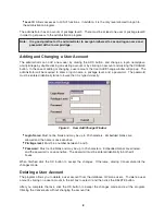
Page 17: ...Figure 2 User Add Change Window Login Name Must not be blank and may be up to 20 characters Embedded blanks are allowed and the name is case sensitive Privilege level Must be a number between 0 and 9 Password Must not be blank and may be up to 20 characters Embedded blanks are allowed and the password is case sensitive The password must be entered identically in both edit boxes When finished click...

Page 18: ...sion to keep track of all ValVue users so that we may notify you of any changes or important information about new software features and updates To register your software you will have to contact Masoneilan and provide your name company name contact information the disk serial number and the installation ID number from the ValVue displays A Masoneilan customer service person will provide you with ...

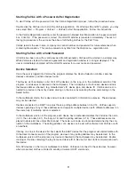
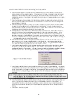
Page 19: ...is program for 60 days Clicking OK will bring a window with the warning message for remaining days to run ValVue without a password Click OK again to continue The LOGON window appears Enter the appropriate name and password assigned by a ValVue administrator in the LOGON window and click OK to continue ValVue will pop up the Device Selection window and search devices connected and list the devices...

Page 20: ...ltiplexer The list displays a line for each device and lists the device address channel tag manufacturer s ID device type and device ID ValVue can be con nected to a device in the list by double clicking on the line or by selecting the line and clicking on the Select button In the multiplexer mode the nodes and sub nodes are listed for information purposes These devices may not be selected Devices...

Page 21: ...he Burst Mode button to bring the Burst Mode Control window to allow the user to turn burst mode on or off for any selected device on the device list The window below will be shown Click the appropriate button to turn burst mode off or on using the HART command 1 or 3 then click OK to accept the selection and exit the window Click the Mux Setup button to bring the Mux Setup window which allows the...

Page 22: ...an send commands to a HART device as a primary master or as a secondary master In most cases the selection between the two does not matter since using ValVue with a device that is communi cating with another HART master is discouraged When used with a multiplexer however operation with a second HART master such as a DCS system is allowed The ValVue program must be config ured to match the configur...

Page 23: ...vice SVI OFFLINE on the list of Device List in the Select Device window Using the offline feature allows access to ValVue screens even if there is no HART modem or multiplexer connected to a computer serial port When SVI OFFLINE is selected you are prompted to select a dump file containing configuration and calibration data of the SVI to run The SVI OFFLINE serves two purposes Allow a user to view...

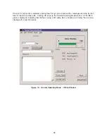
Page 24: ...he revision level of the SVI and dump file Clicking OK pops up the Normal Operating Mode window OFFLINE in green is displayed indicating that ValVue is using a SVI dump file to simulate a SVI rather than commu nicating with a real SVI device 15 Figure 10 Normal Operating Mode Offline Window ...

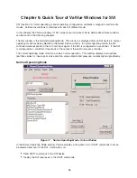
Page 25: ...rmal operating mode the SVI controlled valve responds to the 4 20 mA input signal if the SVI is configured as a positioner If the SVI is configured as a controller it responds to the output of the built in process controller The normal operating mode monitors a valve s normal operation This window displays and updates real time values for input signal valve position valve setpoint and pressure num...

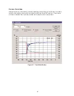
Page 26: ...l Operating window brings up the Process Trend Data window which records valve position and valve setpoint over the last 90 seconds If the process controller is enabled then a process variable and its setpoint will also be recorded 17 Figure 12 Trend Data Window ...

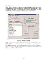
Page 27: ...ion setpoint From manual operating mode the SVI can be switched to Configure Calibrate or Diagnostics mode The Manual Mode window shown below displays and updates real time values for valve position and actuator pressure As in the Normal Operating Mode window ValVue provides a drop down list of HART commands that you can select and send to the SVI ValVue lets you send HART commands to the SVI devi...

Page 28: ...figuration parameters The Tag page is displayed when entering configuration mode This page allows the user to examine and modify the tag descriptor message final assembly number date and polling address The Options page is displayed by clicking the Options Tab in the SVI Configuration window A typical Options page is shown below This page allows the user to choose and set positioner characteristic...

Page 29: ...al Setup page is presented here This page allows the user to choose and set configuration parameters such as air to open or close valve single or double acting actuator process controller on or off direct or reverse position and pressure fault limits 20 Figure 16 SVI Configuration Setup Window ...

Page 30: ...After completing configuration in the SVI Configuration window click OK button to accept the change download to the SVI and exit to manual mode Cancel button to discard the change and exit to manual mode Calibration Clicking the Calibrate button in the Manual Mode window will retrieve current calibration data from the SVI and display them in the SVI Calibration window Calibration mode is used to s...

Page 31: ...ition Controller Parameters The Tuning page is displayed by clicking the Tuning Tab in the SVI Calibration window figure 19 This page allows the user to examine position controller parameters and tune the positioner automatically or manually The user can also open the valve position control loop and manually set an output to the built in I P in SVI The output feature is used to adjust the bias of ...

Page 32: ...Factory button returns the calibrations to those that were set before delivery of the SVI The currently measured values of the primary input signal secondary input signal if the process con troller is enabled and output pressure are displayed and can be compared to reference signals to determine whether re calibration is necessary After completing calibration from a page click OK button to accept ...

Page 33: ...between 1 and 10 this number is approxi mately proportional to the valve size in inches and click the Standard button in the Diagnostics window The slower this test is performed 1 being the slowest speed the better the valve diagnostics It is important to re test a valve at the same speed number for comparison of diagnostic information The diagnostic procedure strokes the valve over its full range...

Page 34: ...n Valve Signature window fig ure 22 will appear with a current valve signature depicted as two red curves The standard valve signa ture graph also provides access to the saved and factory signatures from previous tests stored in SVI s non volatile memory 25 Figure 22 Valve Signature Window ...

Page 35: ...n Speed and click the Extended button to begin test The test result is presented in the Diagnostic Graph window A step response of valve position can be used to examine the dynamic characteristics of a valve sys tem The step response test is run over the user specified range of valve travel ValVue produces a Position vs Time graph after the test A step response appears in Diagnostic Graph window a...

Page 36: ...ure test select Pos Signature in the Type list box enter values in the Start Current and End Current boxes click the Extended button to begin test The test result is presented in the Diagnostic Graph window typ ical positioner signature figure 24 Controller SVI has a built in PID process controller which can be enabled in configuration mode if the controller option is purchased ValVue provides int...

Page 37: ...Automatic L Local Automatic or M Manual button on the left top of the window Operation data of valve position and actuator pressure are displayed on this window If the process controller is configured for ratio control both the measured setpoint and the remote setpoint calculated are displayed in their corresponding engineering units From the Controller Monitor window the controller mode can be sw...

Page 38: ...or window Clicking the Positioner View button figure 25 returns to the positioner view where the valve position can be monitored When the controller is configured in local or remote automatic mode the positioner is operating in normal operating mode and clicking the positioner view button will return the user to the Normal Operating Mode window If the controller is in manual mode the Position View...

Page 39: ...ent Sensor Error Reference Voltage Error Self Check Failure Software Error When SVI is in failsafe mode ValVue will detect it during mode transfer and display the FAIL SAFE MODE window figure 27 In this window HART command 136 Read Status can be sent to the device to determine out the problem In this case Position Error caused by air supply loss is the reason the SVI failed Once the problem is fou...

Page 40: ...ing up a window representing SVI in either normal or manual operating mode depending on the current SVI mode Figure 28 below shows an example of the Normal Operating Mode window ONLINE is displayed in the Window indicating communication with the SVI has been estab lished and valve tag is shown in Tag field Valve Monitoring The Normal Operating Mode window monitors a valves normal operation This wi...

Page 41: ...red under ON LINE in the normal and manual operating windows The user should send the SVI a Read Status message Command 136 and the status codes will be displayed in the response box Sending the SVI a Clear Status Command 138 message will clear these status codes if the prob lem no longer exists and the READ ADDITIONAL STATUS message will go away Reading Configuration and Calibration Data In the N...

Page 42: ... more detail To reset to the default range click the right mouse button Process trend can be used to monitor the performance of a positioner With an enabled built in process controller process variable and its setpoint are also recorded in the process trend Therefore the trend can also be used to test tune and monitor the process loop Since the process trend update rate is 1 to 2 seconds the trend...

Page 43: ...alve signature graphically depicts Travel versus Pressure in both open and close directions This window can display up to three valve signatures current in red saved in blue and factory in black A valve s signature can be turned on or off by clicking the corresponding check box To zoom on any area of the display enter X and Y axis limits and press Tab or click in another box on the screen Alternat...

Page 44: ...l pop up the Report File Selection dialog box Click Browse buttons to select a RTF file with the desired fields and an application to process the RTF file Click the OK button to accept these choices To create the report select Print Report from File menu It may take about 30 seconds to retrieve data from the SVI and start the application to display the created file temp rtf You can edit the file s...

Page 45: ...0 When this output is between 1900 and 2100 or between 3400 and 3600 the bar color changes to yellow When this value is below 1900 or above 3600 the bar color changes to red When the valve is positioned between 1 and 99 and is in steady state the current to I P is stable and normally between 2100 and 3400 with a bar in green color There are a lot of factors that affect this the bias value like env...

Page 46: ...ng the Open button The SVI must be restarted after a restore of the SVI memo ry Position sensor calibration Find Stop is usually required if a dmp file is created from another SVI Going to Other Modes Going to Manual Mode In manual mode the valve does not respond to the input signal and you can manipulate the valve through ValVue Before beginning configuring calibrating or diagnosing the SVI must ...

Page 47: ...de depending on the current SVI mode Clicking the Manual Mode button from Normal Operating window switches SVI to the Manual Mode window figure 33 ONLINE will be displayed in the Manual Mode Window indicating communication with the SVI has been established and valve Tag Number will be shown in Tag Number field Valve Monitoring Manual Mode window monitors a valve operation in manual mode similar to...

Page 48: ...click OK the setpoint is set at 55 0 and the valve will move toward the new setpoint Drag the triangle in the bar graph to a desired position The position setpoint to be set is indicated beside the P button Release the mouse to set the new setpoint Clicking on each side of the triangle in the bar graph moves the valve by 5 The following action fills valve actuator to the supply pressure or exhaust...

Page 49: ...ration button to return to normal operating mode It is important to switch SVI to normal operating mode first before exiting to Device List window so the valve responds to the input signal Exit to Device List Window ValVue can directly return to Device List window from manual mode and leave a SVI in manual mode if desired Select Exit from File menu to exit to Device List window directly Going to C...

Page 50: ...e Tag page of the SVI Configuration window The SVI Configuration window has four tabs Tag Options Setup Controller Clicking a tab shows the corresponding page to examine and modify configuration parameters After making your choices from a page click Tag Options Setup or Controller tab to continue examine and modify configuration OK button to accept the change download to SVI and exit to manual mod...

Page 51: ...ign the assembly a unique number for their internal use Date This field contains a user entered date value with the format DD MM YY The value is stored inside the device It can be used however the user wishes and is often used to track the date of the last valve maintenance Polling Address HART can communicate with up to 15 devices on a single pair of wires These devices are distinguished by their...

Page 52: ... input signal is the combination of valve and positioner characteristics SVI smart positioner provides typical characteristics of linear equal percentage and quick opening as well as a user adjustable custom characterization The choice of positioner characteristics should be based on overall loop characteristics The following fields in the Options page are related to SVI posi tioner characteristic...

Page 53: ...ng a point holding the left mouse button down and dragging the cursor to a new position before releasing the mouse button Add a point by clicking the left mouse button at the desired location Delete a point by clicking the point with the right mouse button After configuring the curve click the OK button to accept the value and exit the Custom Characterization window or click the Cancel button to e...

Page 54: ...ust be the selected configuration option to use the generated curve This option is selected automatically when the user clicks OK to accept the displayed curve To configure custom linearization click the Custom Linearization button The Custom Linearization win dow will appear figure37 Two types of linkages are modeled simple and compound Most linkages use the compound linkage system The simple lev...

Page 55: ...that the SVI parameters cannot be inadvertently changed from the buttons Several levels of locks are provided Allow Local Buttons Buttons on the SVI are fully enabled level 3 Lock Out Local Cal Config The user may use the buttons to perform operations in normal operating mode and manual mode however he she may not go to configure or calibrate mode level 2 Lock Out Local Manual The user may examine...

Page 56: ...full close buttons are selected Near Closed Value This value determines the value of position below which the valve is considered near closed and SVI will record total time the valve stays in near closed region The near closed time is very useful for diagnostic purposes Near closed time is particularly helpful for estimating when it may be time to change the valve trim Pressure Unit and Display La...

Page 57: ...ble or disable the process PID process controller inside SVI When process controller is enabled the process variable must be connected to the auxiliary input channel see SVI operating manual for detail This option is available only if the device has been purchased with the process controller option If the built in process controller is not to be used i e SVI is used as a positioner only Process Co...

Page 58: ...losed Closed Configurable Hardware Reverse Open Closed Configurable Software Reverse Closed Closed Configurable Air To Close Electrical Failure Air Failure Sensor Failure Direct Open Open Configurable Hardware Reverse Closed Open Configurable Software Reverse Open Open Configurable Fail to Low High Signal to I P This selection is activated only if Hardware Reverse or Software Reverse are selected ...

Page 59: ... and Time 2 must be no less than 5 seconds Time 1 must be no less than 1 second or equal to 1 to disable the alarm function Time 1 should be set at least as long as the time required to fully open the valve from fully close or fully close the valve from fully open Otherwise unnecessary position errors may be reported The maximum time limit for both Time 1 and Time 2 is 327 seconds Controller Page ...

Page 60: ...n Clicking a tab brings you a corresponding page Range Tuning or Signal Cal tab to continue examine and modify calibration OK button to accept changes entered download to SVI and exit to manual mode Cancel button to discard changes entered and exit to manual mode Note that finding valve stops Auto Stop Limits and Manual Stop Limits Auto Tune Reset to Factory and any of the signal calibrations in t...

Page 61: ...the Low Signal is 12 00 mA instead of 4 00 mA High Signal mA This is the value in mA of the primary analog input that corresponds to fully open for air to open valve or fully close for air to close valve for a SVI configured as a positioner A typical value is 20 00 mA However if a valve is split ranged for example 4 00 to 12 00 mA the High Signal is 12 00 mA instead of 4 00 mA Supply Pressure Air ...

Page 62: ...es the open position stop exceeds the nominal travel of the valve By entering a value in the Open Stop Adjustment and clicking the Auto Stop Limits or Manual Stop Limits button to run the calibration the valve position can be adjusted to nominal travel For a valve with fully close and open corresponding to its mechanical stop the value is simply 100 Otherwise you may use the following procedure to...

Page 63: ...ing control You can manually adjust these parameters based on the Autotune results or based on trial and error method The Step Profile test available from diagnostic mode is useful to tune the positioner and check its performance Clicking the Auto Tune button starts the procedure to automatically determine the positioner tuning parameters To run Auto Tune smoothly and successfully it is important ...

Page 64: ... Auto Tune The position controller is a type of non linear PID controller with eight adjustable parameters The maximum range of the positioner parameters is as listed below For typical values see the parame ters description 55 Figure 41 Diagnostic Graph Typical Step Response Note For a SVI positioner system using air booster or quick exhaust the Auto Tune may fail and manual adjustment of the posi...

Page 65: ...djusted by adding Padj to P when the valve actuator is exhausting The common values are ranging from P 2 to P 2 Increasing air supply pressure and re running Auto Tune will typically reduce P and increase Padj Beta Beta is a nonlinear gain factor ranging from 8 to 9 When beta is 0 the controller gain is linear Otherwise the gain is the function of error The larger the beta the smaller the gain for...

Page 66: ...the valve is positioned approximately at mid range and the valve remains nearly motionless 4 Click the Output button again the light should go off and the valve returns to its position prior to this procedure 57 Auto Tune Error Code Message Action 0 Self tuning is successful Check the step response 33 Fail in open loop test Check if an air booster or quick exhaust is Used Check the supply pressure...

Page 67: ...o those that were set before delivery of the SVI The currently measured values of the primary input signal secondary input signal if the process con troller is enabled and output pressure are displayed and can be compared to reference signals Clicking any of the buttons Primary Signal Secondary Signal or Pressure starts the calibration proce dure for their respective sensors The procedure will ask...

Page 68: ...pply off From the man ual mode select full open or full closed whichever fills the actuator to supply pressure Go to the signal calibration page and start the pressure calibration procedure Turn the air supply off to get the low value and turn the air supply back on to get the high value After complete calibration from a page click OK button to accept changes entered download to SVI and exit to ma...

Page 69: ...connection to the valve and running the test again This allows the user to pin point the problem to either the actuator or the valve The results of the Standard Valve Diagnostic test include Friction Stroking Time open and closed Upper and Lower Spring Range and Upper and Lower actuator Pressure Range The standard diagnostic is useful for trending valve performance Extended Actuator Signature The ...

Page 70: ...ic data from the SVI and display them in Continuous Diagnostic Data box in the Diagnostics window These data include Total Travel Valve travel accumulated in the unit of number of full strokes Number of Cycles The number of times the valve travel changes direction Time Open The time the valve has spent fully open Time Closed The time the valve has been fully closed Time Near Closed The time the va...

Page 71: ...for valves with medium actuators Higher speeds will be required for larger actuators During the test if the valve moves too slowly or stops moving completely stop the procedure and restart it with a higher speed number The speed number is approximately associated with the size of the valve For example enter a speed of 2 for a 2 inch size valve When the test is finished maximum friction the compute...

Page 72: ...atures The Saved and Factory signatures are stored in SVI s non volatile memory Saved Signature The user may choose to save one valve signature curve Selecting this box plots the last saved valve signature in blue Factory Signature Selecting this box plots the valve signature saved when the SVI was first mounted on the valve To display the signatures check any of the three boxes Current Signature ...

Page 73: ...ser must be logged on with a privilege level of 9 Exit Button Click this button to exit the Valve Signature window and return to the main Diagnostics window Extended Actuator Signature The extended actuator signature test is run over the user specified range of valve travel The minimum range is 10 The positions may range from 5 to 105 with the ranges outside of 0 100 providing data from atmosphere...

Page 74: ...rt Position box then ramps to the end position specified in the End Position box After reaching the end position it returns to the original position In the second part valve moves to the end position then ramps to start position at the specified speed After reaching at start position it returns to the original position and fin ishes the test The results appear in the Diagnostic Graph window as ill...

Page 75: ... 50 3 Enter a value in the End Position box e g 60 4 Enter a value between 2 and 10 seconds in the Time box 5 Click the Extended button to begin test 6 Read the warning message from a pop up window and click the OK button to continue 7 Wait until the test is finished During the test the valve moves from original position to the start position specified in the Start Position box first then move to ...

Page 76: ...lue in the Start Current mA box e g 4 3 Enter a value in the End Current mA box e g 20 4 Enter a value between 2 and 20 in the Samples box e g 10 5 Click the Extended button to begin test 6 Read the warning message from a pop up window and click the OK button to continue 7 Wait until the test is finished During the test the valve responds to the simulated current which ramping from start current t...

Page 77: ...ame tag name are saved in a single file Each entry is time stamped To save test data click the corresponding Show Valve Signature button to review the graph and then exit it Click menu Record and pick the appropriate one from the following list Save Valve Signature Save Saved Signature Save Factory Signature Save Actuator Signature Save Positioner Signature Save Step Profile The following window f...

Page 78: ...g the valve signature graph To display an extended test graph click the Extended button Follow the same procedure as above to pick the desired graph and click the Show Valve Signature button to display the graph Exporting Signatures to Spreadsheets In addition to running ValVue in offline to retrieve test data saved in a text file these data can also be read into a spreadsheet or other similar pro...

Page 79: ... to the device to find out the problem After the problem is fixed the device can be restarted by either resetting the power or clicking the reset button in manual mode Fault Message Following is a list of problems which may cause SVI go to failsafe mode Position Error Position Sensor Error Current Sensor Error Reference Voltage Error Self Check Failure Software Error When SVI is in failsafe mode V...

Page 80: ...n Error Band should not be config ured too small 2 to 10 is typical and Time 1 and 2 should be larger than the time required to stroke the valve from fully close to fully open and from fully open to fully close If these parameters are set appropriately loss of air supply or insufficient air supply is probably the reason that causes a position error The active range of a standard SVI position senso...

Page 81: ...indow In each of these windows ValVue provides a drop down list of HART commands that you can select and send to the SVI as illustrated in the Figure below The HART commands are used as follows 1 Select a command from the drop down list 2 Click the Send Message button to send the selected HART command to the SVI device 3 SVI response to the selected HART command is displayed in the Response Box 72...

Page 82: ...mmon Practice Commands Provide functions common to many field devices but not all Device Specific Commands Provide functions that are unique to a particular field device Following list commands available for a user to select and send to SVI by clicking the Send Message button 000 Read Identifier Returns the unique identifier from the device including manufacturers ID 101 Masoneilan device ID devic...

Page 83: ...message is written to the SVI 018 Write Tag and Descriptor Selecting this command brings up a dialog which lets a user enter a tag and descriptor message and date The data is written to SVI 019 Write Final Assembly Selecting this command brings up a dialog which lets a user enter a final assembly number This number is written to SVI Masoneilan Extended Commands include 210 Read Configuration Reads...

Page 84: ...d within the SVI RESET_OCCURRED A reset has occurred either because of a power interruption or because of an external request for reset DATA_OVERRUN The SVI is not processing acquired data INTERNAL_TEMP_ERROR Internal temperature of the SVI is above or below the rated temperature EEPROM_WRITE_FAILED A write to the SVI s internal memory failed FIND_STOPS_FAILED The calibration procedure for positio...

Page 85: ...arameters used by the process controller including lower and upper setpoint limits lower and upper alarm limits output rate limit dead zone setpoint tracking on or off and derivative source PV or error 219 Read Loop Parameters 2 Displays the values of parameters ratio control gain and bias used by the process controller for ratio control 220 Read Loop Mode Read the process controller mode for the ...

Page 86: ...rt Format File and A Generated Report section The user can create different format files to generate different reports To create a custom SVI report a user needs to create a text or rich text format file that is laid out in the format of the desired report ValVue will substitute the value of its parameter into the text file wherever it finds a parameter name that matches an SVI parameter For examp...

Page 87: ... box to pop up a window to select a proper program to use NotePad and WordPad are often installed in the directory c Program Files Accessories or in c win dows The actual location of these files or Microsoft Word program will vary from computer to comput er Click OK in the Report Format File Selection window to accept these choices and exit the window The final step to create the report is to retr...

Page 88: ...ssemblyNum AssemblyNumber MfgID MfgID DeviceType DeviceType DeviceID DeviceID HWRev HWRev SWRev SWRev PollingAddress PollingAddress Dynamic Information Position Position Pressure Pressure Signal Signal Setpoint Setpoint ProcessVar ProcessVar Temperature Temperature Bias Bias Output Output Mode Mode ContModeSP ControllerModeSP ContModePV ControllerModePV SignalPercent SignalPercent Configuration In...

Page 89: ...arClosed PresUnits PresUnits PosUnits PosUnits PVUnits PVUnits SPUnits SPUnits Language Language Calibration Information StartupMode StartupMode InitialSetpoint InitialSetpoint ControllerRate ControllerRate RatioControl RatioControl ContrDirRev ContrDirRev LowSignal LowSignal HighSignal HighSignal HighPres HighPres LowPV LowPV HighPV HighPV LowSP LowSP HighSP HighSP P P I D Padjust Padjust Beta Be...

Page 90: ...ResponseClosed LSprRngSaved LSprRngSaved USprRngSaved USprRngSaved LSprRngFac LSprRngFac USprRngFac USprRngFac Controller Information ContP ContP ContI ContI ContTD ContTD ContKD ContKD ContBeta ContBeta LSPLimit LSPLimit USPLimit USPLimit LowAlarm LowAlarm HighAlarm HighAlarm ManResetBias ManResetBias OutRateLim OutRateLim ContDZ ContDZ DevSource DevSource AlarmType AlarmType SPTracking SPTrackin...

Page 91: ... General Information Tag FV 101 Descriptor FLOW CONTROL Date 11 JAN 1999 Message COOLING WATER FLOW AssemblyNum 20 MfgID Dresser DeviceType 200 DeviceID 0 HWRev 7 SWRev 1 PollingAddress 0 Dynamic Information Position 53 2 Pressure 12 25 Signal 12 51 Setpoint 1 R ProcessVar 1 R Temperature 68 Bias 3108 Output 0 Mode NORMAL ContModeSP Local ContModePV Remote SignalPercent 53 2 Configuration Informat...

Page 92: ...lue 100 0 LLimitStop OFF LLSValue 0 0 NearClosed 5 0 PresUnits psi PosUnits PVUnits gal min SPUnits gal min Language English Calibration Information StartupMode Startup Local InitialSetpoint 50 00 ControllerRate 1 00 RatioControl OFF ContrDirRev Direct LowSignal 4 0 HighSignal 20 0 HighPres 30 00 LowPV 0 00 HighPV 200 00 LowSP 0 00 HighSP 200 00 P 172 I 48 Padjust 19 Beta 3 PosComp 5 DeadZone 0 00...

Page 93: ...actory 10 0 20 0 30 0 40 0 50 0 60 0 70 0 80 0 90 0 Position 4 9 6 6 8 4 10 2 12 0 13 7 15 5 17 3 19 2 Act Pres Up 4 0 5 8 7 4 9 3 10 9 12 6 14 6 16 1 18 2 Act Pres Down SigFactorySpeed 2 Friction 0 61 LSpringRange 2 74 USpringRange 20 44 ResponseOpen 1 50 ResponseCl 2 00 LSprRngSaved 2 92 USprRngSaved 20 61 LSprRngFac 2 72 USprRngFac 20 55 Controller Parameters ContP 20 ContI 3 ContTD 0 ContKD 8 ...

Page 94: ...uration data from the SVI and present them in the SVI Configuration window Turning Process Controller On To enable the built in process controller go to the Setup page of the SVI Configuration window The Setup page appears when clicking the Setup Tab in the SVI Configuration window A typical Setup page is shown below This page allows the user to choose and set configuration parameters such as air ...

Page 95: ...r than 3 seconds the SVI will perform a cold start where its memory is restored from parameters stored in non volatile memory This option determines the initial controller mode after start up Startup Local This option sets the controller in local mode after SVI startup Startup Remote This places the controller in remote mode after SVI startup Startup Last Mode This sets the controller in the mode ...

Page 96: ...asured Setpoint Ratio Bias The Ratio Gain and Ratio Bias are set in the Controller Parameters window PV Units Code The user may select the units for the process variable and setpoint HART defines unit codes for many commonly used units ValVue is programmed to recognize many of these and the user can select them from the list box If the unit used is not in the list box the user can type the HART un...

Page 97: ...ler Monitor window Click the Set Param button to enter the Controller Parameters window to finish controller configuration and set initial PID parameters see Chapter 17 4 Tune the process control loop to refine PID parameters Process trend graph can be used in the tuning process The controller must first be configured in configuration mode see Chapter 15 before calibrating the controller Clicking ...

Page 98: ...ing units This edit box is enabled only for a SVI with the built in PID process controller High Remote Setpoint This is a value in engineering unit that corresponds to the High Signal of the primary analog in mA SVI uses High Remote Setpoint values to convert the primary input signal in mA to Remote Setpoint in engineering units This edit box is enabled only for a SVI with the built in PID process...

Page 99: ...to recalibrate the primary and secondary signals and output pressure sensors in the SVI These sensors are calibrated at the factory and do not usually require re calibration but if needed this page provides a convenient method to perform signal calibration The Reset to Factory button returns the original sensor calibra tions to the value set when the SVI was manufactured The currently measured val...

Page 100: ...e with a 250 ohm resistor actually used Changing the value of the resistor calls for re calibration of the secondary sig nal since the secondary signal sensor actually measures voltage rather than current Clicking a tab brings up the corresponding page to examine and modify calibration parameters and initi ate calibration procedures After complete calibration from a page click OK button to accept ...

Page 101: ...ters 4 Tune the process control loop to refine PID parameters The process trend graph can be used in the tuning process while adjusting PID parameters Controller Monitor The Controller Monitor window figure 57 shown on page 93 is a graphic interface for the SVI process controller Pressing the Controller View button which is activated when the controller is enabled in either the Normal Operating or...

Page 102: ...tic Mode In this mode controller output is calculated based on the error between process variable and local setpoint that is adjustable manually Manual Mode In this mode controller output is kept constant until manually adjusted It is no longer calculated by the PID algorithm In this illustration the controller is in local automatic mode with local setpoint at 80 00 gpm process variable at 80 00 g...

Page 103: ...tput by 5 If the S button beside the Set Point box is enabled the previous controller mode is in local automatic Otherwise the previous mode is remote automatic The local setpoint value can be changed if the S button is enabled and the setpoint tracking is not selected Click the S button type a setpoint value in the popup Input Data window and click OK The setpoint is set and is used at the moment...

Page 104: ...e setpoint at the moment of the transfer Otherwise the value of local setpoint is set to the last local setpoint or initial setpoint if this is the first time in local automatic mode upon power being applied to the SVI controller Remote Automatic to Manual Control Click the M button to make this transfer The red mode light moves to M button The controller output remains unchanged at the moment of ...

Page 105: ...e measured setpoint and process variable Before the transfer compare the values of remote and process variable displayed in the window so the impact of the transfer can be estimated before the transfer Manual to Local Automatic Control Click the L button to make this transfer The red mode light moves to the L button The controller output remains unchanged at the moment of the transfer If the optio...

Page 106: ...top window and pressing Tab or click in another box in the window You can also dragging the mouse over part of the graph to zoom in to see the details To reset to the default range simply click the right mouse button Process trend can be used to monitor the performance of both controller and positioner The trend can be used to test tune and monitor the process loop The trend data window is a model...

Page 107: ... Parameters win dow figure 60 The maximum range of the controller parameters is as listed below Typical values for each of the parameters is shown in the parameter descriptions 98 Figure 60 Controller Parameters Window Parameter Range Proportional Gain 0 to 1000 Integral Time 0 to 1000 seconds Derivative Time 0 to 32 seconds Derivative Gain 2 to 100 Beta 9 to 9 Hi Lo Setpoint Limits 25 above hi PV...

Page 108: ... in process variable units is used in the PID calculation to compute the error Low and High Alarm Limits Define when the alarm lights on the controller view will be lit If absolute alarms are selected and the process variable is not between the low and high alarm limit the alarm light will be on If deviation alarms are set and the difference between the setpoint and the process variable is not bet...

Page 109: ... Mode Clicking the Positioner View button returns to the positioner view where the valve position can be moni tored When the controller is in local or remote automatic mode the positioner is in normal operating mode and clicking button will return the user to the Normal Operating Mode window If the controller is in manual mode the button will return the user to the Manual Mode window Exit to Devic...

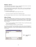
Page 110: ...rface Additionally the multiplexer supports the multidrop connection of HART devices on a single loop Therefore using the multidrop feature it is possible to expended capacity of a system beyond 7936 HART devices For more information regarding the MTL multiplexer refer to the manufacturer s documents and ValVue Mux Connection Guide ValVue Multiplexer Options Using the multiplexer version of ValVue...

Page 111: ...Hide Background is selected the ValVue background is hidden Otherwise the back ground will cover the whole screen The device list may be saved in a file in order to eliminate the necessity of re scanning each time con nect is selected Unless the option of Load Device Addresses from File is selected the file used is tem porary and a re scan is done each time the program is restarted If selected the...

Page 112: ...5 characters for the node of MTL multiplexer Retry Count The number of times the multiplexer will retry sending a command to a Hart device before returning with an error The valid range for this number is 0 to 5 3 is the recommended number for use with ValVue Preamble Count The number of preambles prefixed to each Hart command sent to a device The valid range is 2 to 20 3 to 5 is the recommended v...

Page 113: ...mmand to a node of the multiplexer The user will be prompted for the node that is to be reset When reset the multiplexer node will re scan all of the devices connected to the node this hardware re scan is different from the re scan done by ValVue from the Re scan button Depending upon the options set for the multiplexer this may take a while to complete No communication may be done with devices on...

Page 114: ...di Arabia Telephone 966 3 341 2446 Fax 966 3 341 2447 Telex 832146 SJ Dresser Al Rushaid Valve Instrument Co Ltd DARVICO P O Box 10145 Jubail Industrial City 31961 Saudi Arabia Telephone 966 3 341 0278 Fax 966 3 341 7624 AUSTRIA Masoneilan HP HP GmbH Hans Kudlich Strasse 35 A2100 Korneuburg b Wien Austria Telephone Fax 43 2262 63689 BELGIUM Masoneilan Division of Dresser Europe S A 281 283 Chausse...

Reviews: