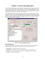
Process Controller
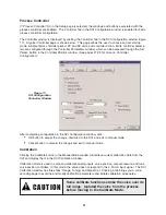
If “Process Controller” On in the Setup page is selected, the windows and buttons associated with the
process controller are enabled. The Controller Tab in the SVI Configuration window is enabled for basic
process controller configuration.
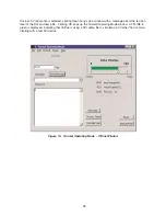
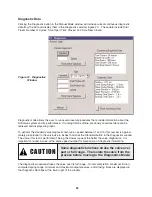
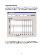
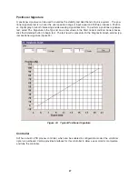
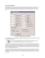
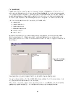
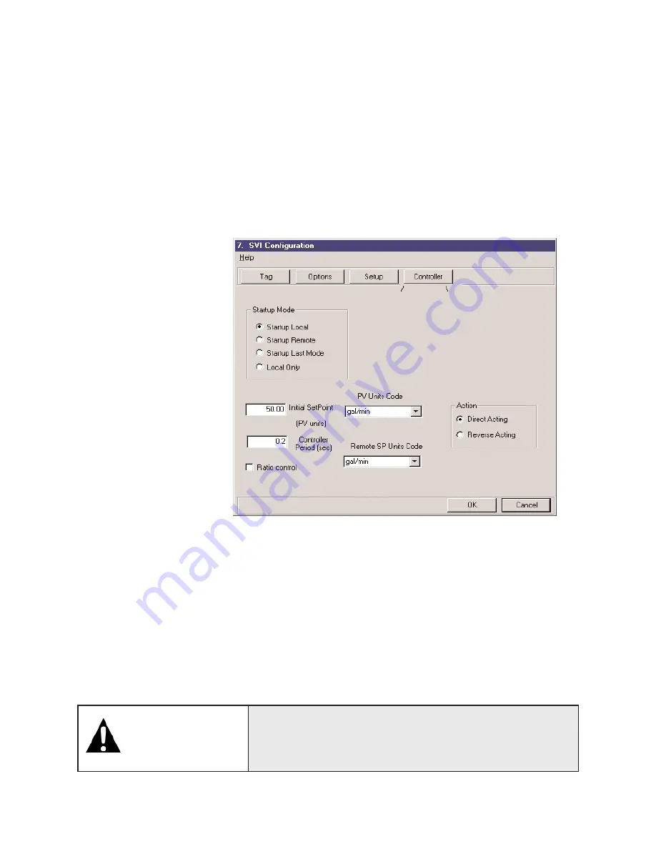
The Controller window is displayed by clicking the Controller Tab in the SVI Configuration window (figure
17). A typical Controller page is shown below. This page allows the user to choose and set startup
mode, initial setpoint, controller period, PV and SP units, and controller action. More controller parame-
ters are configured through the Controller Parameters window, which can be accessed through the Set
Param. button in the Controller Monitor window. (See pages 27-29 for more on Controller
Configuration).
After completing configuration in the SVI Configuration window, click
•
OK button to accept the change, download to the SVI, and exit to manual mode
•
Cancel button to discard the change and exit to manual mode
Calibration
Clicking the Calibrate button in the Manual Mode window will retrieve current calibration data from the
SVI and display them in the SVI Calibration window.
Calibration mode is used to scale and calibrate analog inputs, valve position, output pressure, and tune
valve position controller. In this mode, the valve does not respond to the 4-20 mA input signal. The SVI
Calibration window has three tabs: Range, Tuning, and Signal Cal. Clicking a tab brings you a corre-
sponding page to examine and modify calibration parameters and initiate calibration procedures.
21
Some calibrate functions stroke the valve over its
full range. Isolated the valve from the process
before moving to the Calibrate Mode.
Figure 17.
SVI Configuration
Controller Window
CAUTION


