background image

Summary of Contents for RCS

Page 1: ...er at least two weeks in advance and confirm by your purchase order Standard charges will be made IDProvide for adequate safeguards against accidents to persons working on or near equipment during both in stallation and operation See PRECAUTIONS iiiInstall all equipment correctly Foundation design must be adequate and piping carefully done Use recom mended accessories for operating protection IiIM...

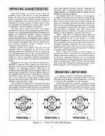
Page 2: ...each impeller and pushes them through to the discharge The pumping capacity of a lobe blower operating at a con stant speed therefore remains relatively independent of reasonable inlet or discharge pressure variations To change capacity it is necessary either to change speed or rotation or vent some of the air No attempt should ever be made to control capacity by means of a throttle valve in the i...

Page 3: ...mospheric corrosion before installation The maximum 3 period of internal protection is considered to be one year under average conditions if closing plugs or seals are not removed Protection against chemical or salt water at mosphere is not provided Avoid opening the blower until ready to start installation as protection will be lost quick ly by evaporation If there is to be an extended period bet...

Page 4: ...ace and leveled set the blower on it without bolting and check for rocking If it is 4 not solid determine the total thickness of shims required under one foot to stop the rocking Place half of this under each of the diagonally opposite short feet and tighten the mounting studs or screws Rotate the drive shaft to make sure the impellers still turn freely If the blower is to be direct coupled to a d...

Page 5: ... very slight bow appears in the slack side of the belts 5 Stop the motor and compare the tensions of the in dividual belts by pressing down firmly with one hand on the top surface It should be possible to deflect each belt only to the point where its top sur face is even with the bottom of the other underdeflected belts 5 6 A new set of belts should be first tensioned about Va greater than normal ...

Page 6: ...to a cavity in each headplate that is vented and drained downward In addition sealing rings are provided on both shafts where they pass through the inner walls of the headplates These serve to reduce air leakage from or into the air chamber and also minimize oil carryover into the air chamber They are not sufficiently effective to enable the blower to handle gases however Oil sumps on each each en...

Page 7: ... 14 15 16 17 18 19 20 21 POSSIBLE CAUSE Speed too low Wrong rotation Obstruction in piping Speed too low Excessive pressure Obstruction in piping Excessive slip Speed too high Pressure too high Impellers rubbing Inadequate lubrication Excessive lubrication Excessive pressure Coupling misalignment Excessive belt tension Misalignment Impellers rubbing Worn bearings gears Unbalanced or rubbing impell...

Page 8: ...ile it is operating or while subject to accidental starting Cover external moving parts with adequate guards 8 II1II Disconnect power before doing any work and avoid by passing or rendering inoperative any safety or pro tective devices II1II If blower is operated with piping disconnected place a strong coarse screen over the inlet and avoid standing in the discharge air stream II1II Stay clear of ...

Page 9: ...ferences or casing rubs toresult from shifts in the blower mounting or from changes in piping support Foreign materials sucked into the blower will also cause trouble which can only be cured 9 by disconnecting the piping and thoroughly cleaning the blower interior If this type of trouble is experienced and the blower is found to be clean try removing mounting strains Loosen blower mounting bolts a...

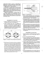
Page 10: ... away from the shaft when it releases Stand to one side and provide rags or cushioning material under the gear 10 Figure 5 Gear Removal 4 Remove bearing clamp plates 54 by unscrewing cap screws 32 and removing lockwashers 35 Group the shims 10 and the wavy spring washers 29 with each clamp plate and tag for ease of reassembly 5 Remove the headplate remove all capscrews holding the headplate to the...

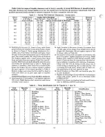
Page 11: ...en clamping plates 34 and bearing outer race Place shims 10 as required to get this clearance Then fasten the clamping plates to the headplate with capscrews 32 and lockwashers 35 Note The 400 drive end drive bearing has a bearing clamp spacer 53 included in the clamping arrange ment Be sure the bearing clamping plates are located 11 so the oil feed groove will be up and toward the bear ing when t...

Page 12: ...e the drive shaft by hand to make sure there are no gear tight spots or impeller contacts 14 Apply Locktite to the screw threads the washer faces an both sides of the slinger then install drive end oil slinger 40 flatwasher 36 and tighten capscrew 60 to torque value in Table 4A Caution Keep fingers away from impellers and gears 13 Install gearbox 3 with gasket 7 and tighten capscrews 23 evenly Not...

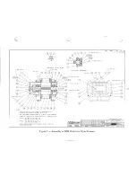
Page 13: ...EW THREADS AND BOTH FACES OF WASHER AND SLINGER J 1 400 ONLY SEE NOTE 63 I 9 SEE NOTE No 5 37 SEE NOTE No REF 64676023 rr w jw M r Ji iff J O tRO C oU F REVISEDPER fivE 9 3 tro V MITt b6 1 1 3 E REVISED PER EeN RVE 1998 34 36 V DB Ar V Fe 5 CS 8E o ITEM 63 600 ONLY REVISED REM e7 367 VFC DLBo fi7 E C REMOVED ITEM 36 WASHER REM B OViEL PIN DIMENSION ADDED REM A IADDEO 409 AND ABOVE EMI fi Sj 7 J 1 ...

Page 14: ... APPLY LOCKTITE TO SCREW THREADS AND BOTH FACES OF WASHER AND SLINGER 406 DRIVEN SHAFT ARRANGEMENT SEE NOTE No 3 19 409 412 22 REF 64677023 P INTS AU LO N O sUaJECT TO RflURN UPON O NDANO THTHE PRtiUCONO fIONr r THU LLIIOr EU OIN HT vpnR NuLTD 0 II I U u a o y I M 40g A J SEE NOTE No 3 SEE NOTE No 5 nREM D 2 fi V R f CM r Rm AP 09 86 E 5iXAS B47102J oV DAn ri i CHAn u 6 I 0 Figure 7 Assembly of Re...

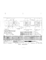
Page 15: ...00 I oo I 00 116 I 00 00 y t OIL DRAIN PLUG W INLET 6 FLG S FLG O FLG W DISCHARGE AD SHEAVE WIDTH 8 00 10 00 11 15 14 20 6 00 9 0 AE SHEAVE DIAMETER 13 0 16 00 8 12 11 00 8 314 10 314 10 7 8 9 ALL DIMENSIONS IN INCHES 1 13 1 13 1 31 U V KEYWAY W WI IAA I ADI AElcA bLITY 1 8 1 50 2 15 375x lEE 3 01 PT 3 o1 PT 16 0013 5316 50132 5 FL OZ I 2 cD 00 00 4 1 PT 4 01 PT oo oo Z60 00 00 4 N 1 4 01 PT 15 50...

Page 16: ... h 1 F t 17 I If I 7Ci F IF IrF m171 44132 441 9CDIFi911 975 R7 1 l xl 44140 4 41 1 113 7 1 CERTIFIED CORRECT FOR J I KIM N 10 I P ml 441 e I F qll 9 1 Ie I I h C I 1 R c 1 1I m n I I 117 1 63 1 c F 17 C I 7 1 r7 Iql4 c F 11F CiT or V RFI T nRTVF nATA CUSTOMER ORDER No _________ R F T S nQ T 1 C I 11 1 ROOTS ORDER No Ig 67 CE DATE u c J U L C __ 1 13 1 13 1 31 U V KEYWAY W I WI IAAIABI AOIAElrAJJA...

Page 17: ... Q 0 9 0 e vii 17 3 Q 0 Q 0 0 a x W 0 Q I J OJ LL fp ...

Page 18: ...SERVICE RECORD Date Service Notes I 18 ...

Page 19: ...NO QTY PART DESCRIPTION 400 600 7 2 Gasket 10 1 Shim Set 14 3 Bearings 27 4 Seals Headplate 28 4 Sealing Ring 33 1 Seal Dr Shaft 37 2 Oil Level Gauge 38 3 Sleeve 39 1 Sleeve 52 1 Bearing 55 2 Air Filters NOTES See pages 13 14 for reference number 19 ...

Reviews: