16
|
Dresser Roots
Maintenance/Replacements
A good program of inspection and maintenance servicing, if
followed consistently, is the most reliable means of prevent-
ing costly repairs to a blower. A simple record of procedures
and dates will help maintain this work on a regular schedule.
Basic requirements are lubrication and cleaning, along with
periodic checking for increased vibration and hot spots on
the cylinder. Inlet and discharge pressures and temperatures
should be observed frequently, to minimize the chances for
trouble resulting from blower ratings being exceeded.
Above
all, the unit must be operated within its specifications.
In a blower properly installed and operated, there is no
moving contact between the two impellers, or between the
impellers and cylinder or headplates. Wear is then confined
to the timing gears, the bearings which support and locate
the shafts, and shaft seals. All are lubricated, and wear
should be normal if they are always supplied with clean, high
grade lubricating oil. Shaft seals, weather lip type or rotating
mechanical type, are subject to deterioration as well as wear.
They may require replacement at varying periods. O-rings
should be replaced at each disassembly.
If trouble should occur during operation, and its cause cannot
be readily determined, consult the TROUBLESHOOTING
CHECKLIST. Remedies suggested there can usually be
performed by qualified mechanics, using procedures detailed
in this manual. Major repairs not covered here are considered
beyond the scope of maintenance, and should be referred
to the nearest Sales Office. See listing on the last page.
Warranty failures
should not be repaired at all, unless
specific approval has been obtained through a Sales Office
before starting the work. Unauthorized disassembly within the
warranty period may void the warranty.
Where repairs involve parts replacement, it is recommended
that Factory Parts be used to insure fit and suitability. Delay
in making such repairs can be reduced by having spare parts
on hand.
When ordering parts, please furnish all information from the
blower nameplate.
Repairs or adjustments to blowers should be performed by
personnel with a good background of general mechanical
experience and the ability to follow the detailed instructions
in this manual. Some operations involve extra care and a
degree of precision work. This is especially true in timing
impellers, and in handling bearings. Experience indicates
that a high percentage of bearing failure is caused by dirt
contamination before or during assembly. Therefore, clean
the work area before starting disassembly, and protect new
or reusable parts during progress of the work.
The following detailed work procedures cover repairs and
adjustments that can normally be handled successfully at the
installation site. Numbers shown in brackets ( ) correspond
to Item Numbers used in the sectional assembly drawings
and in Table 9. Refer to the drawing applying to the type unit
being repaired while reading the instructions.
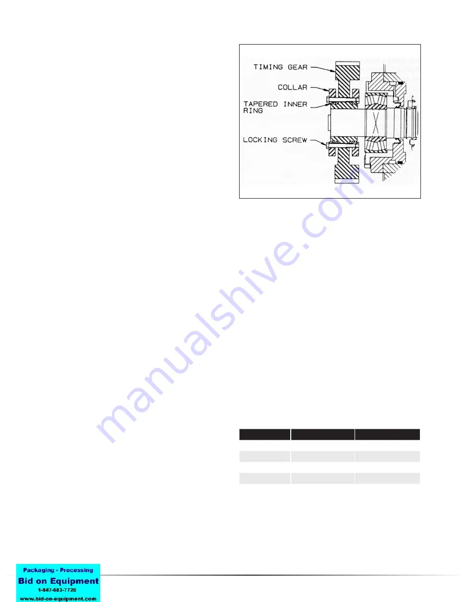
A - REMOVING GEARS WITH GEAR LOCKING
ASSEMBLIES
1. Drain oil at plug (67) near bottom of gearbox (3).
2. Loosen cap screws (30) attaching gearbox to headplate
3. Attach lifting device to support gearbox and remove
capscrews. Move gearbox out of way.
4. Match mark gears so that they can be returned to the
same shafts in same position.
5. Gradually release gear locking assembly capscrews
evenly all round. Initially each screw should be released
about a quarter of a turn only to prevent tilting and jam-
ming of collars. DO NOT REMOVE LOCKING SCREWS
COMPLETELY OR THE COLLAR MAY SPRING OFF
CAUSING INJURY. Just loosen the locking assembly,
both collars should be loose on the tapered inner rings.
To loosen the back collar, tapping on the locking screws
may be necessary. To loosen the front collar, use of
wedges between the collar and the gear web may be
required
6. Using two puller holes in the gear (see Table 6 for size)
pull the gears off the shafts,
B - INSTALLING GEARS WITH GEAR LOCKING
ASSEMBLIES
1. Apply NEVERSEEZ paste on the gear locking device
screw threads, under the screw heads, on the tapered
rings, on the collar tapers, and on the gear hub outside
diameters.
Figure 6 - Gear Locking Assembly
Table 6 - Puller Hole Sizes
Blower Size
Gear Puller Hole Size Carrier Puller Hole Size
1000
1/2/13
5/8/11
1200
3/4/10
5/8/11
1400, 1600
8-Jan
3/4/10
1800, 2000
1-1/4 - 7
8-Jan
Summary of Contents for Roots DVJ WHISPAIR
Page 22: ...DVJ WHISPAIR Dry Exhauster 23 Figure 15 Assembly of 10 thru 12 DVJ V V Belt Drive Splash Lube ...
Page 23: ...24 Dresser Roots Figure 16 Sectional Assembly of 10 thru 14 DVJ V Blowers ...
Page 24: ...DVJ WHISPAIR Dry Exhauster 25 Figure 17 Sectional Assembly of 16 20 DVJ Common Lube ...
Page 25: ...26 Dresser Roots Figure 18 Sectional Assembly of 1016 DVJ V Units ...


