20
|
Dresser Roots
On a belt-drive unit with extended shaft, use spacer
sleeve (62) to push inboard bearing (60) into its final
position. There is no shaft shoulder behind this bearing,
but there is a stop for the sleeve. Make sure that the
inner race flange of bearing (60) is facing outboard.
2. Install bearing lockwasher (25) and locknuts (24) on each
shaft, and tighten nuts with a spanner wrench. Lock the
nuts by bending a tab on each washer into a slot in the
nut.
3. Install new or original gears and set impellers as
described in Operation B.
4. Place bearing clamp plate (8) over main bearing (31)
and tighten all screws. In the case of the extended type
drive shaft, end cover (58) serves as the clamp plate but
cannot be installed until later.
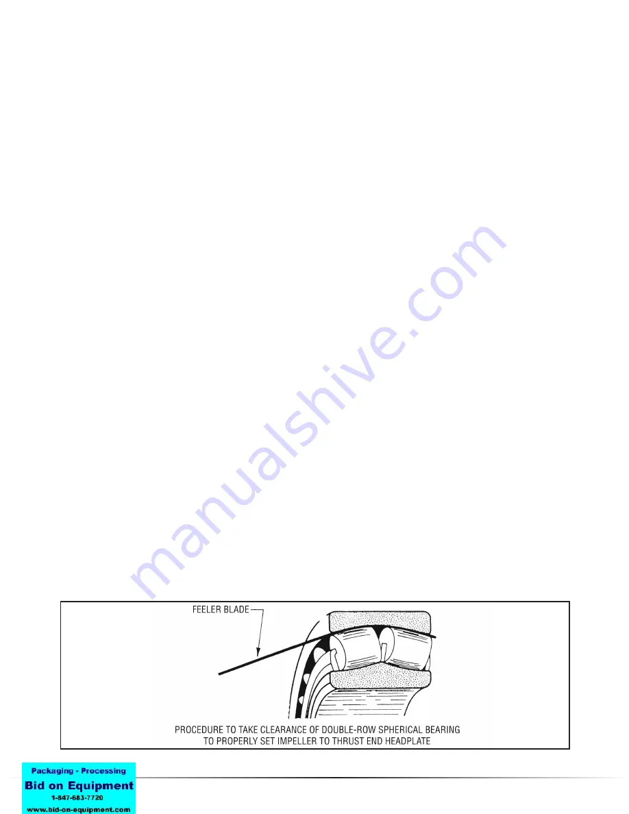
5. Using 1/2” (13mm) feeler gauges, determine for each
of the drive end bearings (31) the maximum clearance
between the outer race and one of the rollers near the
top. Obtain pieces of brass shim stock, of thicknesses
corresponding to these clearances, about 3/4” (19mm)
wide and long enough to reach completely through the
bearings. Push one piece through each bearing, in the
spaces between rollers, then rotate that shaft so that one
roller of each row is up on the shim stock. This removes
all clearances, and forces the bearing rollers and races to
center as in normal running. Refer to Figure 14.
6. Set the impellers lengthwise in the case by using long
pieces of shim stock, or feelers, as wedges between the
two ends of each impeller and the headplates. Using the
total end clearance obtained in Step 8 of Operation D,
the two ends of each impeller and the headplates. Using
the total end clearance obtained in Step 8 of Operation
D, place wedges equal to two-thirds of the total at the
gear end and one-third at the drive or thrust end. It will
be necessary to bump the shafts to obtain the required
impeller positions. Set the drive end clearance first, after
installing and tightening drive shaft end cover (58) if used.
7. With feeler gauges, carefully measure the spaces
between the drive end bearing carrier flanges and the
headplate face. Insert shims (17) of correct thickness to
fill these spaces. The original shims should be correct if
bearings and carriers have been returned to the original
location.
8. Remove wedges from ends of impellers inside the casing.
9. Tighten all bearing carrier flange screws.
10. Recheck impeller end clearances for proper values
per tables, then remove brass shim stock from both
bearings (31).
11. Check front and back clearances of impeller lobes as
outlined in Operation C, and reset timing if not correct.
12. Reassemble the unit, starting by installing the main end
cover (5) and then proceeding in reverse order through
Operation A from Step 5. Be careful with lip seal (23) or
new O-ring (59) in end cover (5).
13. Check the work area to make sure no parts have been
left out in assembly.
14. Turn the drive shaft over several times by hand as final
check for impeller contact or case rubs.
15. Reinstall coupling or belt sheave, check their alignment
with driver and reconnect all external piping.
16. Start and operate unit for a reasonable period in the
manner outlined for initial starting. See OPERATION.
IMPELLER CLEARANCES
Instructions on impeller clearances under Operation C and
Operation D do not include data on the amount of clearance
to be expected. For blowers in good condition this informa-
tion is not essential in field service work. However, situations
may arise where it is desirable to compare existing clearances
with the correct values. Listed in Table 8 or 9 are the ranges
of values used in original factory assembly. Clearances may
change in service, but they should never be less than the
minimum values listed. Only well
qualified personnel
should
attempt to measure clearances for comparison with this data.
Figure 14
Summary of Contents for Roots DVJ WHISPAIR
Page 22: ...DVJ WHISPAIR Dry Exhauster 23 Figure 15 Assembly of 10 thru 12 DVJ V V Belt Drive Splash Lube ...
Page 23: ...24 Dresser Roots Figure 16 Sectional Assembly of 10 thru 14 DVJ V Blowers ...
Page 24: ...DVJ WHISPAIR Dry Exhauster 25 Figure 17 Sectional Assembly of 16 20 DVJ Common Lube ...
Page 25: ...26 Dresser Roots Figure 18 Sectional Assembly of 1016 DVJ V Units ...


