background image

Surepowr Series  

Sure 150

Installation Manual

Table of Contents

Intended of Usage ................................................................... 2
Actuator Range of Application ........................................... 2

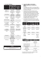
1.  Actuator Marking .....................................................3
2.  Special Conditions for Safe Use  

(ATEX)/Conditions of Certification (IECEx) ............3

3. Ratings ......................................................................3
4. Safety ........................................................................4
Safety First! ........................................................................................... 4
Warnings and Notices ...................................................................... 4
Joint Handling .................................................................................... 4
Fasteners ............................................................................................... 5
Seals ........................................................................................................ 5
Cable Glands ....................................................................................... 5
Grounding and Bonding ................................................................ 5
Spring Housing................................................................................... 5
Enclosure Surface Temperature ................................................... 5
5. Installation................................................................6
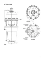
Dimensional Information ............................................................... 6
Dimensional Information ............................................................... 7
Cover Removal and Assembly ...................................................... 8
Mounting .............................................................................................. 8

Horizontal Mounting .............................................................. 8

Conduit Locations and Thread Sizes .......................................... 9
Cable Glands ....................................................................................... 9
Grounding and Bonding ................................................................ 9

Wiring ..................................................................................................... 9

Wiring Diagrams ....................................................................... 9

Mechanical Stop Settings ............................................................11
Limit Switch Settings .....................................................................11

Switch adjustments for clockwise spring fail  

operation (viewed from the top of the actuator) ......11
Switch adjustments for counter-clockwise spring fail 

operation (viewed from the top of the actuator) ......11

Limit Switch Settings (Optional Offering) .............................12

Installation.................................................................................12

6. Operation............................................................... 13
Thermal Overload ...........................................................................13
Duty Cycle ..........................................................................................13
Optional Manual Override ...........................................................13
7. Maintenance .......................................................... 13
Mounting Fasteners .......................................................................13
Enclosure Cover Screws ................................................................13
Seals and Cable Glands .................................................................14
8. Storage ................................................................... 14

RCS Actuators

Summary of Contents for Surepowr Sure 150

Page 1: ...Cover Removal and Assembly 8 Mounting 8 Horizontal Mounting 8 Conduit Locations and Thread Sizes 9 Cable Glands 9 Grounding and Bonding 9 Wiring 9 Wiring Diagrams 9 Mechanical Stop Settings 11 Limit Switch Settings 11 Switch adjustments for clockwise spring fail operation viewed from the top of the actuator 11 Switch adjustments for counter clockwise spring fail operation viewed from the top of th...

Page 2: ...losive Atmospheres Part 17 Electrical Installations Inspection and Maintenance c Any laws decrees standards procedures or other documents related to the area in which the actuator shall be installed Dresser Natural Gas Solutions NGS cannot be held responsible if these standards are disregarded Check the compatibility of the actuator s nameplate markings with the classification of the installation ...

Page 3: ...ent uses M10x1 5 stainless steel special fasteners of grade A4 80 and yield strength 600 MPa If fasteners are replaced they shall be replaced with the equivalent size and grade 2 Some external parts of the equipment are non conducting and may generate an ignition capable level of electrostatic charge under certain extreme conditions Ensure that the equipment is not installed in a location where it...

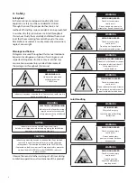
Page 4: ...ation operation or maintenance of the unit CAUTION Indicates a potentially hazardous situation that if not avoided can result in minor to moderate injury or serious damage to the product The situation described in the CAUTION may if not avoided lead to serious results Important safety measures are described in CAUTION as well as WARNING so be sure to observe them Observe these and all other warnin...

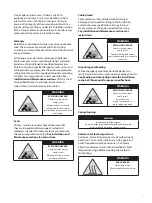
Page 5: ...sealed and replaced as needed Failure to do so may compromise the enclosure protection rating See Installation and Maintenance sections for instructions WARNING EXPLOSION HAZARD Death or serious injury could result Maintain all seals to ensure enclosure protection Cable Glands Cable glands must be installed and maintained and properly torqued according to the Installation and Maintenance specifica...

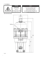
Page 6: ...ce Notice SurePowr actuators can be supplied for clockwise or counter clockwise spring driven rotation viewed from the top of the actuator The spring drive rotation is noted on the actuator name tag and wiring diagram Ensure that the actuator has been supplied with the proper spring drive operation for the application prior to installation on the driven device Dimensional Information Figure 1 ...

Page 7: ...7 Dimensional Information Figure 2 ...

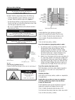
Page 8: ...n specified screw torque may compromise the enclosure protection rating Under normal operation the capacitor will discharge prior to the removal of the cover Enclosure cover screw specifications Exd or EEx d versions 8 10mm x 1 5 x 35 mm A4 80 Stainless steel apply anti freeze compound torque to 32 33 ft lbs 43 44 N m WARNING EXPLOSION HAZARD Death or serious injury could result Maintain cover scr...

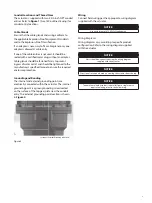
Page 9: ...otection Grounding and Bonding The internal and external grounding points are electrically connected within the actuator The internal grounding point is a green grounding screw located on the surface of the top gear plate near the conduit entry The external grounding point location is shown in Figure 4 Location of External Grounding with Screw Figure 4 Wiring Connect field wiring per the appropria...

Page 10: ...10 ...

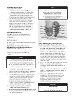
Page 11: ...otor stop Cam 4 Cam 3 Cam 2 Cam 1 Cam Setscrews 1 16 inch hex drive Figure 6 Switch adjustments for clockwise spring fail operation viewed from the top of the actuator Cam 1 actuates the clockwise motor stop switch Cam 2 actuates the counter clockwise motor stop switch Cams 3 and 4 are auxiliary switches To set the clockwise spring fail position switch a Ensure the actuator is positioned in the cl...

Page 12: ...uator to the device Ensure the actuator is centered properly with the device shaft and then tighten all bolts and nuts evenly d Remove the cover bolts located around the actuator motor and control cover flange e Terminate field wiring per the appropriate RCS wiring diagram supplied with the actuator Use a minimum of 18 AWG stranded wire NOTE Ensure the driven device is properly positioned in its f...

Page 13: ...e disengaging Manual Override Do not disengage Manual Override while the hand wheel is under load 7 Maintenance WARNING HIGH ENERGY HAZARD LOADED SPRING Death or serious injury could result Do not attempt to repair the actuator unless properly trained in specific repair methods for this device Only qualified certified and properly trained personnel shall conduct actuator maintenance The gear train...

Page 14: ... they are tightening according to specifications to prevent ingress of water or dirt Routinely check that cable glands are tightened to the manufacturer s specified torque to ensure the required enclosure protection WARNING EXPLOSION HAZARD Death or serious injury could result Maintain cable gland torque specifications to ensure enclosure protection 8 Storage The Surepowr actuator must be stored i...

Page 15: ...15 ...

Page 16: ...he right to make changes in specifications and features shown herein or discontinue the product described at any time without notice or obligation Contact your Dresser Natural Gas Solutions representative for the most current information The Dresser Logo and all Trademarks containing the term Dresser are the property of Dresser LLC a subsidiary of Baker Hughes a GE Company www dresserngs com RCS S...

Reviews: