


MAINTENANCE
SECTION 5
Page 19
DRESSTA
OM515C520C99/1E
system).
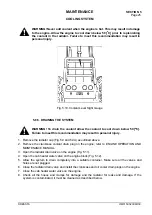
5.7. BRAKES
5.7.1. SERVICE BRAKE SYSTEM
This machine utilizes a split type hydraulic brake system whereby a common dual chamber master
brake cylinder supplies fluid to each axle independently. If a failure occurs in either the front or the
rear axle braking system the other brake system can stop the machine. The master cylinder is
located beneath the floorboard in the floorboard in the operator’s compartment (Fig. 5.6).
The service brake is actuated with the brake pedal (the right one) or the brake and transmission
disconnect pedal (the left one) from the operator’s cab. Increasing gradually pressure exerted on
the brake pedal the required braking effect is obtained. The more the pedal is depressed the
stronger the braking effect. As required, there is possibility of braking as described above with the
transmission connected or disconnected. Braking with the transmission disconnected occurs with
all clutches of the transmission released. In such a case the full engine power may be used to
operate the loader hydraulics.
WARNING! When adding brake fluid, wear safety goggles. Fluid contact can
result in serious eye injury.
WARNING! Whenever the brake lines have been disturbed, or if the brake pedal
feels soft or spongy, the brake system must be bled to remove entrapped air.
Consult your distributor.
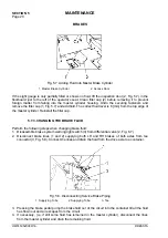
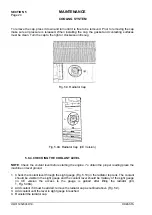
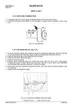
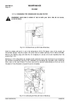
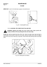
5.7.2. CHECKING THE BRAKE FLUID LEVEL
1
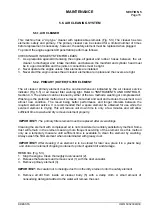
Fig. 5.6. Master Brake Cylinder Sight Gauge (under the floorboard)
Check the sight gauges on the master cylinder (Fig. 5.6). The sight gauges must be completely
filled with fluid.
Summary of Contents for 515C
Page 3: ...OM515C520C99 1E DRESSTA ...
Page 5: ......
Page 7: ......
Page 10: ...SECTION 1 INTRODUCTION ...
Page 12: ......
Page 17: ...SECTION 2 SAFETY PRECAUTIONS ...
Page 19: ......
Page 37: ...SECTION 3 MACHINE TRANSPORT AND STORAGE ...
Page 39: ......
Page 49: ...SECTION 4 OPERATING ...
Page 51: ......
Page 107: ...SECTION 5 MAINTENANCE ...
Page 165: ...SECTION 6 SPECIFICATIONS ...
Page 167: ......
Page 181: ...SECTION 6 SPECIFICATIONS Page 16 OM515C520C99 1E DRESSTA WIRING DIAGRAMS ...
Page 182: ...SPECIFICATIONS SECTION 6 Page 17 DRESSTA OM515C520C99 1E WIRING DIAGRAMS ...
Page 187: ...SECTION 6 SPECIFICATIONS Page 22 OM515C520C99 1E DRESSTA WIRING DIAGRAMS ...


