


MAINTENANCE
SECTION 5
Page 31
DRESSTA
OM515C520C99/1E
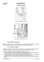
ELECTRICAL SYSTEM
CHARGING FULLY DISCHARGED BATTERIES.
When a machine is not in use for an extended period, the maintenance-free battery can become
discharged. For this reason, when a machine will not be used for over 30 days, it is recommended
that the negative ground terminal cable be disconnected. Prior to starting up a machine that has
been idle, always make a visual inspection of the battery and take an open circuit voltage test.
A reading of 1.23 [g/cm
3
] (75 % of full charge) or less indicates a state of discharge.
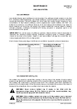
Check amount of charge of batteries:
100% of full charge
1.26 - 1.28 [g/cm
3
]
75% of full charge
1.23 - 1.25 [g/cm
3
]
50% of full charge
1.20 - 1.22 [g/cm
3
]
Fully discharged
1.11 - 1.13 [g/cm
3
]
5.11. ENGINE
WARNING! Wear hand and eye protection when draining hot fluids.
WARNING! Before servicing the engine, be sure the bucket is lowered to the
ground, the transmission direction lever is locked in neutral (N), the parking
brake is applied, electric system master switch is off, and the key removed. Tag
the machine.
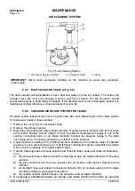
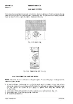
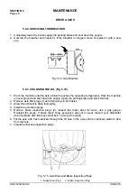
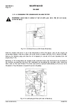
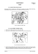
5.11.1. CHECKING THE CRANKCASE OIL LEVEL
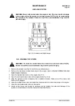
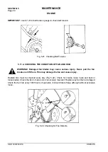
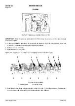
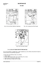
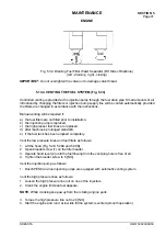
Check the crankcase oil level every day with dipstick (1, Fig. 5.16). In order to do this, lift the hood or
radiator grill (Fig. 5.48, 5.48A and 5.48B). Do not operate the engine if the oil level is below mark L
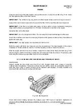
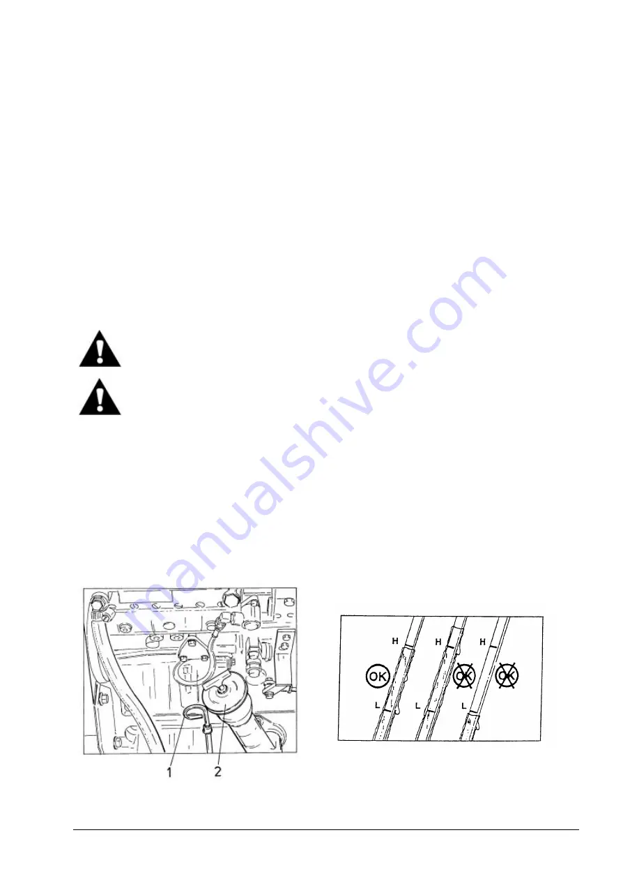
(low) or above mark H (high) on the dipstick (Fig. 5.17). Check the oil level before starting the
engine or at least after 15 minutes after stopping it. This allows the oil to drain back to the
crankcase.
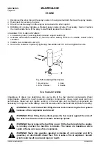
IMPORTANT:
Park the loader on level ground for correct oil level reading.
Fig. 5.16. Checking the Crankcase Oil Level
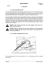
Fig. 5.17. Engine Oil Dipstick
1. Dipstick 2. Filler Port
Summary of Contents for 515C
Page 3: ...OM515C520C99 1E DRESSTA ...
Page 5: ......
Page 7: ......
Page 10: ...SECTION 1 INTRODUCTION ...
Page 12: ......
Page 17: ...SECTION 2 SAFETY PRECAUTIONS ...
Page 19: ......
Page 37: ...SECTION 3 MACHINE TRANSPORT AND STORAGE ...
Page 39: ......
Page 49: ...SECTION 4 OPERATING ...
Page 51: ......
Page 107: ...SECTION 5 MAINTENANCE ...
Page 165: ...SECTION 6 SPECIFICATIONS ...
Page 167: ......
Page 181: ...SECTION 6 SPECIFICATIONS Page 16 OM515C520C99 1E DRESSTA WIRING DIAGRAMS ...
Page 182: ...SPECIFICATIONS SECTION 6 Page 17 DRESSTA OM515C520C99 1E WIRING DIAGRAMS ...
Page 187: ...SECTION 6 SPECIFICATIONS Page 22 OM515C520C99 1E DRESSTA WIRING DIAGRAMS ...


