SECTION 5
MAINTENANCE
Page 36
OM515C520C99/1E
DRESSTA
ENGINE
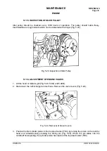
Fig. 5.25. Positioning a Cylinder Piston in TDC
IMPORTANT:
When the piston is positioned in its TDC remove the pin so as not to cause damage
to the pin or engine.
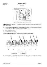
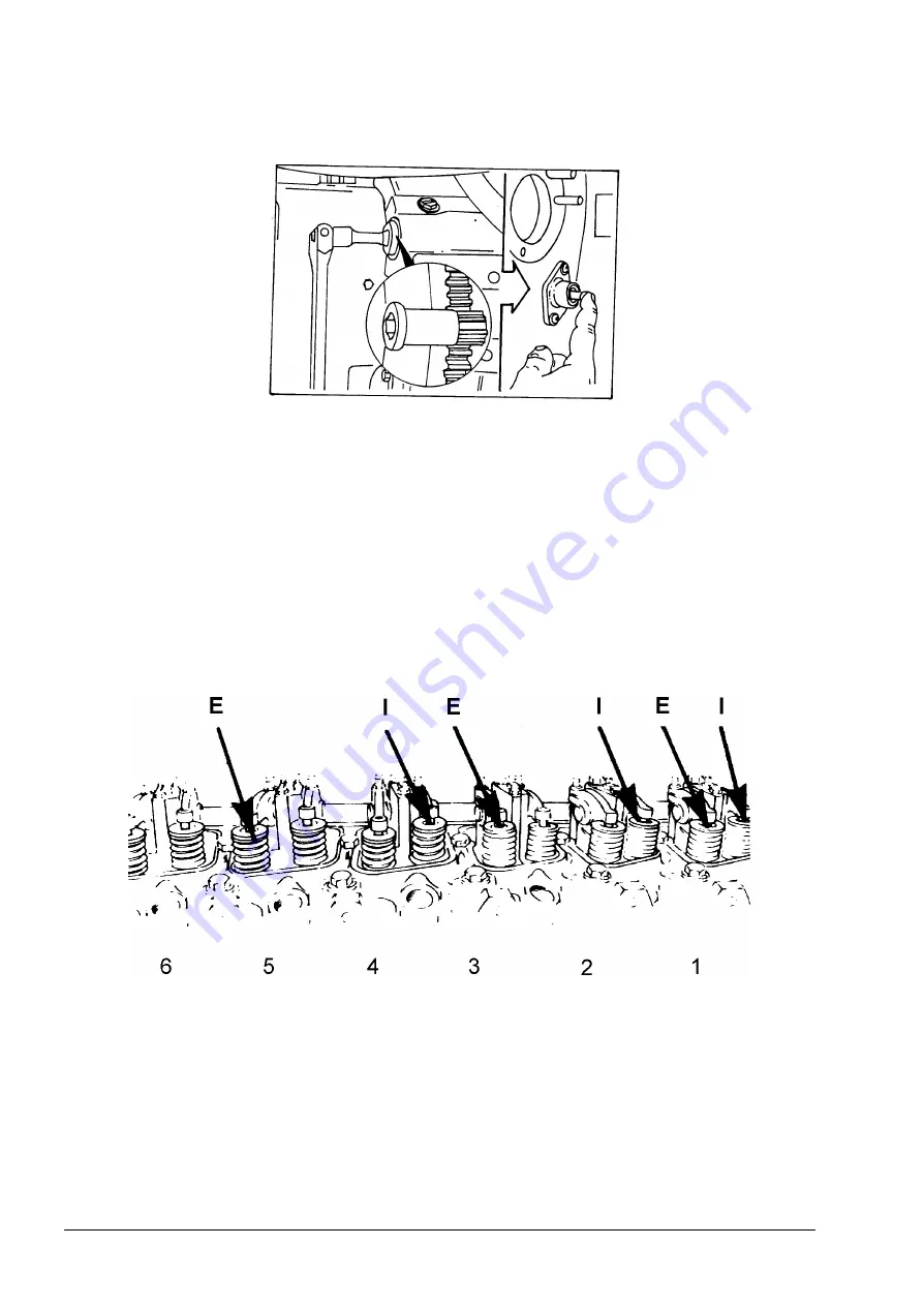
4. Check and adjust, if necessary, the valve lash as shown in Fig. 5.26. Use a screw driver and
a wrench. The value of the valve lash should be as follows:
•
Suction valve (I): 0.25 [mm],
•
Exhaust valve (E): 0.51 [mm].
Tighten the adjusting nut up to the torque of 24 [Nm] and check the lash again.
Fig. 5.26. Engine Valves
1. Suction Valves
2. Exhaust Valves
5. Mark the position of the vibration damper, rotate it by 360 [º]. Check and adjust, if necessary,
the other valves as shown in Fig. 5.27 as described in item 4 above.
Summary of Contents for 515C
Page 3: ...OM515C520C99 1E DRESSTA ...
Page 5: ......
Page 7: ......
Page 10: ...SECTION 1 INTRODUCTION ...
Page 12: ......
Page 17: ...SECTION 2 SAFETY PRECAUTIONS ...
Page 19: ......
Page 37: ...SECTION 3 MACHINE TRANSPORT AND STORAGE ...
Page 39: ......
Page 49: ...SECTION 4 OPERATING ...
Page 51: ......
Page 107: ...SECTION 5 MAINTENANCE ...
Page 165: ...SECTION 6 SPECIFICATIONS ...
Page 167: ......
Page 181: ...SECTION 6 SPECIFICATIONS Page 16 OM515C520C99 1E DRESSTA WIRING DIAGRAMS ...
Page 182: ...SPECIFICATIONS SECTION 6 Page 17 DRESSTA OM515C520C99 1E WIRING DIAGRAMS ...
Page 187: ...SECTION 6 SPECIFICATIONS Page 22 OM515C520C99 1E DRESSTA WIRING DIAGRAMS ...

