SECTION 5
MAINTENANCE
Page 44
OM515C520C99/1E
DRESSTA
HYDRAULIC SYSTEM
5.14.2. CHANGING THE HYDRAULIC SYSTEM OIL
Operate the boom, bucket and steering circuits until the hydraulic oil becomes warm.
1. Park the machine on level ground, lower the bucket flat on the ground. Stop the engine, and
apply the parking brake. Lock the front and rear frames.
2. Remove plug (9) from reservoir drain valve (10). Fit a short threaded ¾ [''] pipe connector into
the end of a piece of hose (enclosed in accessories). Screw the pipe connector into the drain
valve. Put the other end of the hose into a container large enough to hold the oil from the
reservoir. DO NOT open the drain valve yet!
3. Clean the top of the reservoir with kerosene or cleaning solvent.
4. Slowly open drain valve (4).
5. Start the engine. Raise the bucket completely, and roll the bucket all the way back.
6. Shut the engine down. Switch off the electric system master switch.
WARNING! NEVER work or walk under a raised bucket without proper blocking
in raised position.
7. Open drain valve (10), allow the reservoir to drain.
8. Lower the boom slowly. After the boom comes to rest on the ground, push the bucket lever
forward to ”dump” position. This will force the hydraulic oil out of the boom and bucket cylinders
and into the reservoir (standard version only).
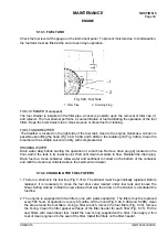
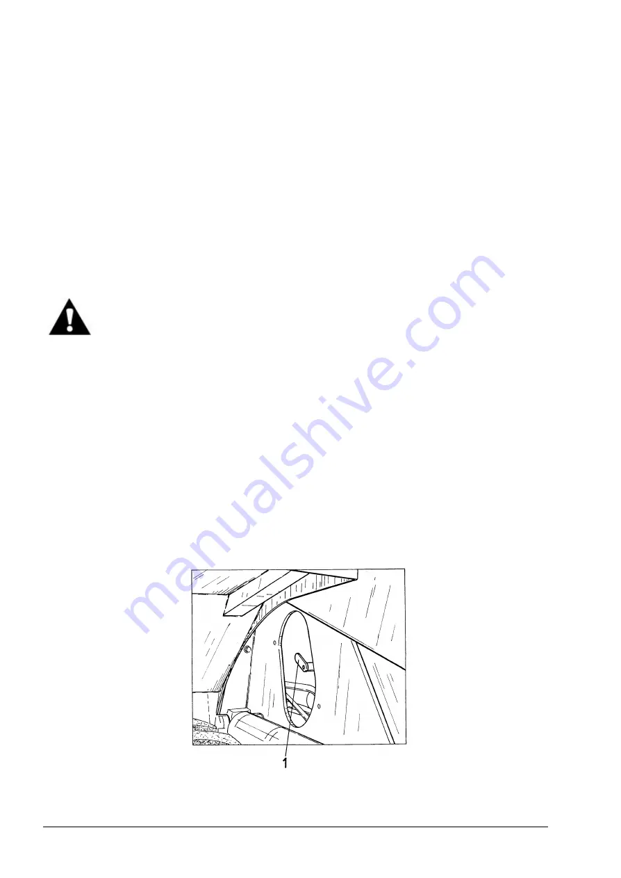
8a. Lower the boom of a CE version with a boom safety valve (Fig. 5.36).
9. Close drain valve (10) after the reservoir has drained.
10. Remove the drain pipe and hose from the drain valve. Install plug (9) into the drain valve.
11. Replace reservoir filter (7) as described in section 5.14.3.
12. Fill the reservoir with clean oil until the ball in sight gauge (13) reaches the top of the gauge.
Refer to Chart 2 and 3 for the grade of oil specified.
13. Install and tighten filler cap (4).
14. Start the engine and operate the boom and bucket to fill the hydraulic cylinders with oil.
15. Lower the bucket to the ground and shut down the engine. Check the oil level as described in
section 5.14.1.
Fig. 5.36. Boom Safety Valve (on RH Side of Machine)
1. Valve Lever
Summary of Contents for 515C
Page 3: ...OM515C520C99 1E DRESSTA ...
Page 5: ......
Page 7: ......
Page 10: ...SECTION 1 INTRODUCTION ...
Page 12: ......
Page 17: ...SECTION 2 SAFETY PRECAUTIONS ...
Page 19: ......
Page 37: ...SECTION 3 MACHINE TRANSPORT AND STORAGE ...
Page 39: ......
Page 49: ...SECTION 4 OPERATING ...
Page 51: ......
Page 107: ...SECTION 5 MAINTENANCE ...
Page 165: ...SECTION 6 SPECIFICATIONS ...
Page 167: ......
Page 181: ...SECTION 6 SPECIFICATIONS Page 16 OM515C520C99 1E DRESSTA WIRING DIAGRAMS ...
Page 182: ...SPECIFICATIONS SECTION 6 Page 17 DRESSTA OM515C520C99 1E WIRING DIAGRAMS ...
Page 187: ...SECTION 6 SPECIFICATIONS Page 22 OM515C520C99 1E DRESSTA WIRING DIAGRAMS ...

