SECTION 5
MAINTENANCE
Page 52
OM515C520C99/1E
DRESSTA
TRANSMISSION SYSTEM
5.18.4. CLEANING THE TRANSMISSION SUCTION STRAINER
The location of the suction strainer is shown in Fig. 5.43.
1. The transmission should be drained as described under Par. 5.18.2. Install the drain plug.
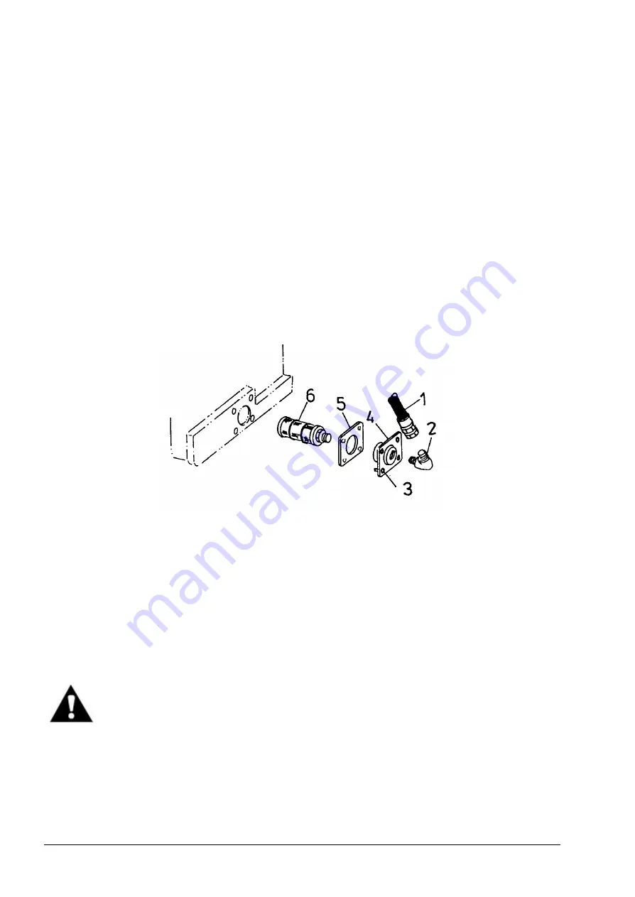
2. Disconnect tube (1, Fig. 5.45) from elbow (2), then loosen bolts (3), remove retainer (4) with
strainer assembly (6) from the transmission housing, and remove gasket (5).
3. Thoroughly clean the gasket material from the transmission housing and retainer (4).
4. Unscrew strainer assembly (6) from retainer (4). Look inside the strainer and inspect the valve
spring for breakage. Replace, if necessary.
5. Wash the parts in a commercial cleaning solvent. Remove all particles from the magnetic rods
on the strainer (if there are such particles). If necessary, the rods can be removed. Dry all parts
thoroughly.
6. Install strainer assembly (6) into retainer (4) and apply a new gasket (5) to the retainer. Install
this assembly into the transmission housing. Thread elbow (2) into retainer (4) and tighten.
Attach tube (1) to the elbow.
7. Fill the transmission with oil (Refer to Par. 5.18.2).
Fig. 5.45. Transmission Oil Suction Strainer
1. Tube
2. Elbow
3. Bolts
4. Retainer
5. Gasket
6. Strainer Assembly
5.18.5. SERVICING THE BREATHER
1. Remove the breather located on the RH side of a machine (Refer to Fig. 5.46).
2. Wash the breather in a commercial cleaning solvent to completely remove any sediment in the
cap.
WARNING! Wear eye protection when using air or water under pressure to clean
parts. Limit air pressure to 200 [kPa] and water pressure to 270 [kPa].
3. Dry the breather thoroughly using compressed air. If compressed air is not available, shake to
remove the excess cleaning solvent.
4. Dip the cap in clean engine oil. Allow the excess oil to run out.
5. Reinstall the breather.
Summary of Contents for 515C
Page 3: ...OM515C520C99 1E DRESSTA ...
Page 5: ......
Page 7: ......
Page 10: ...SECTION 1 INTRODUCTION ...
Page 12: ......
Page 17: ...SECTION 2 SAFETY PRECAUTIONS ...
Page 19: ......
Page 37: ...SECTION 3 MACHINE TRANSPORT AND STORAGE ...
Page 39: ......
Page 49: ...SECTION 4 OPERATING ...
Page 51: ......
Page 107: ...SECTION 5 MAINTENANCE ...
Page 165: ...SECTION 6 SPECIFICATIONS ...
Page 167: ......
Page 181: ...SECTION 6 SPECIFICATIONS Page 16 OM515C520C99 1E DRESSTA WIRING DIAGRAMS ...
Page 182: ...SPECIFICATIONS SECTION 6 Page 17 DRESSTA OM515C520C99 1E WIRING DIAGRAMS ...
Page 187: ...SECTION 6 SPECIFICATIONS Page 22 OM515C520C99 1E DRESSTA WIRING DIAGRAMS ...

