SECTION 4
OPERATING
Page 22
OM515C520C99/1E
DRESSTA
CAB DOOR AND WINDOWS
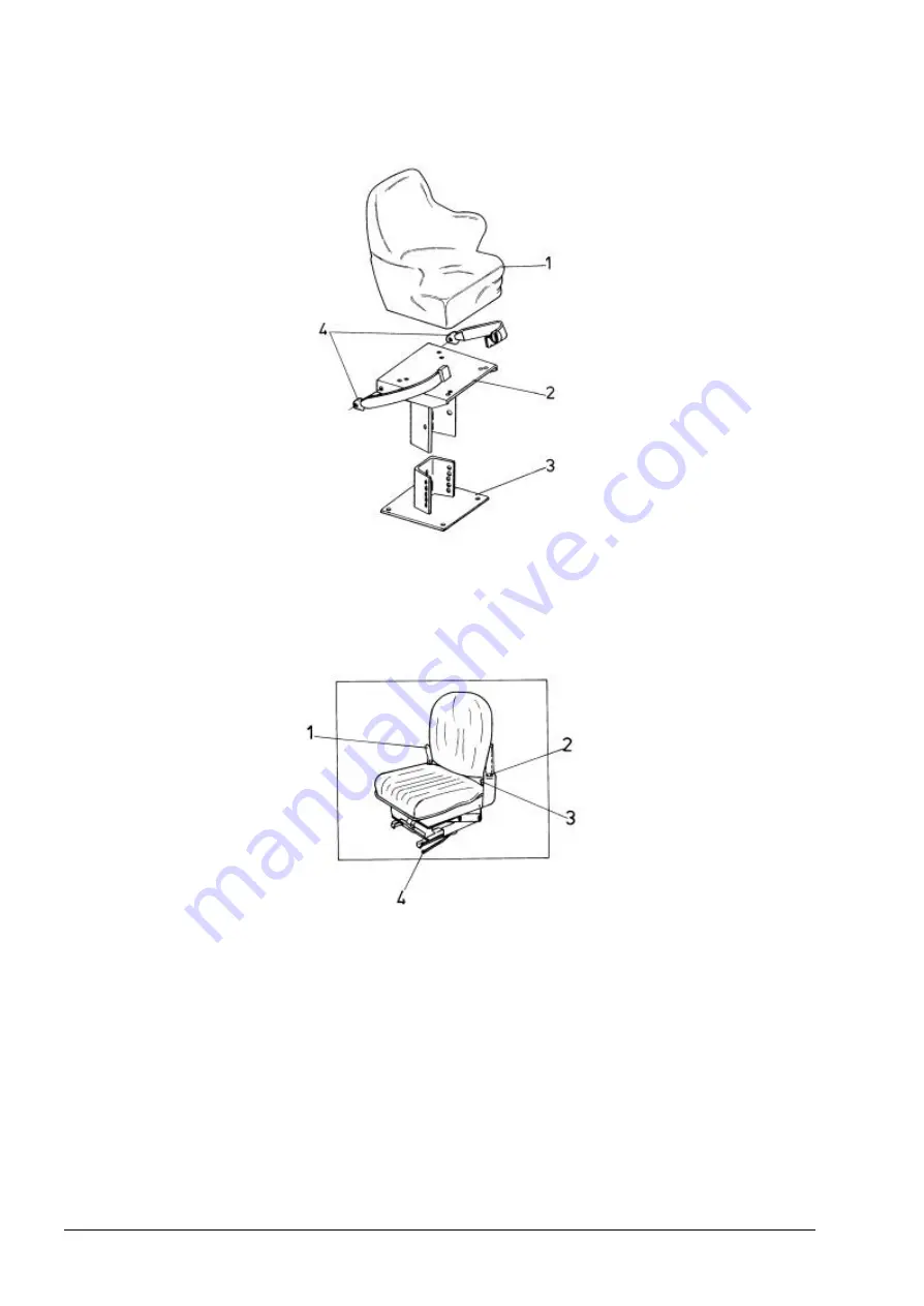
Fig. 4.13. Solid Base Operator’s Seat and its Adjusting Controls
1. Seat
2. Inner Height Adjustment Post
3. Outer Height Adjustment Post
4. Seat belt
SUSPENSION SEAT (VIKING-BOSTROM)
Fig. 4.14. Suspension Seat Adjusting Controls (Viking-Bostrom)
1. Preload Adjustment Ratchet Lever
2. Back Seat Angle Adjustment Catch
3. Seat belt
4. Forward and Rearward Control Lever
For operator’s convenience in reaching the controls and improved operating visibility, the operator’s
seat can be adjusted to various positions. Pull lever (4) back and slide the seat to the desired
forward or rearward position. Release the lever to lock the seat.
To adjust the angle of the back seat cushion, lift up the seat back and tilt it to one of its three
positions. Release the cushion allowing the catches on the seat back to engage in bracket
notches (2).The suspension preload should be adjusted to the operator’s weight for proper ride
control. While sitting in the seat, turn ratchet lever (1) clockwise to increase the preload. Turn the
ratchet counterclockwise to decrease the preload.
Summary of Contents for 515C
Page 3: ...OM515C520C99 1E DRESSTA ...
Page 5: ......
Page 7: ......
Page 10: ...SECTION 1 INTRODUCTION ...
Page 12: ......
Page 17: ...SECTION 2 SAFETY PRECAUTIONS ...
Page 19: ......
Page 37: ...SECTION 3 MACHINE TRANSPORT AND STORAGE ...
Page 39: ......
Page 49: ...SECTION 4 OPERATING ...
Page 51: ......
Page 107: ...SECTION 5 MAINTENANCE ...
Page 165: ...SECTION 6 SPECIFICATIONS ...
Page 167: ......
Page 181: ...SECTION 6 SPECIFICATIONS Page 16 OM515C520C99 1E DRESSTA WIRING DIAGRAMS ...
Page 182: ...SPECIFICATIONS SECTION 6 Page 17 DRESSTA OM515C520C99 1E WIRING DIAGRAMS ...
Page 187: ...SECTION 6 SPECIFICATIONS Page 22 OM515C520C99 1E DRESSTA WIRING DIAGRAMS ...


