SECTION 4
OPERATING
Page 28
OM515C520C99/1E
DRESSTA
4.10. DOME LIGHT WITH SWITCHES
Dome light is installed in the roof of the cab on the right and left hand side of the operator’s head.
The light is equipped with a switch. Two lights are installed on machines in CE version.
4.11. STARTING AND STOPPING THE ENGINE
4.11.1. NORMAL START (AMBIENT TEMPERATURE ABOVE 0 [
°°
C])
WARNING: DO NOT jump on or off the machine. Keep two hands and one foot,
or two feet and one hand in contact with the steps and hand holds at all times.
Always face the machine when climbing on or off to reduce the chances of
slipping and injury.
1. Check that the parking brake switch is applied (machine stopped)
2. Check that transmission direction lever is locked in the "N" (neutral) position.
3. Turn the master electric system switch "ON" (Refer to Fig. 4.22, 4.22.A).
4. With your back against the back rest of the operator's seat, adjust the seat position so that the
brake and decelerator pedal can be easily depressed (Refer to Fig. 4.6).
5. Sound the horn to clear the area of personnel.
NOTE:
All the warning lights should light up while the starting key is between RUN and START
position. Replace any bulb that fails to light up.
NOTE:
The engine will not start while the direction lever is in any position other than "N" (neutral).
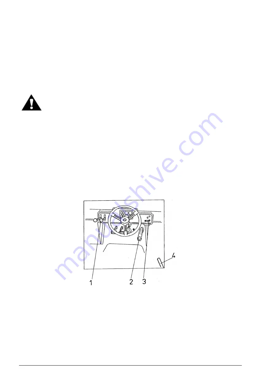
Fig. 4.23. Starting and Stopping the Engine
1. Transmission Direction Lever
2. Accelerator Pedal
3. Starting Switch
4. Parking Brake Lever
6. Turn the starting key from RUN to START position (Fig. 4.3) to start the engine with accelerator
pedal released (idle speed).
7. Keep the key till the engine starts but no longer than 30 seconds. Then release the key
immediately, it returns automatically to the RUN position.
Summary of Contents for 515C
Page 3: ...OM515C520C99 1E DRESSTA ...
Page 5: ......
Page 7: ......
Page 10: ...SECTION 1 INTRODUCTION ...
Page 12: ......
Page 17: ...SECTION 2 SAFETY PRECAUTIONS ...
Page 19: ......
Page 37: ...SECTION 3 MACHINE TRANSPORT AND STORAGE ...
Page 39: ......
Page 49: ...SECTION 4 OPERATING ...
Page 51: ......
Page 107: ...SECTION 5 MAINTENANCE ...
Page 165: ...SECTION 6 SPECIFICATIONS ...
Page 167: ......
Page 181: ...SECTION 6 SPECIFICATIONS Page 16 OM515C520C99 1E DRESSTA WIRING DIAGRAMS ...
Page 182: ...SPECIFICATIONS SECTION 6 Page 17 DRESSTA OM515C520C99 1E WIRING DIAGRAMS ...
Page 187: ...SECTION 6 SPECIFICATIONS Page 22 OM515C520C99 1E DRESSTA WIRING DIAGRAMS ...


