OPERATING
SECTION 4
Page 31
DRESSTA
OM515C520C99/1E
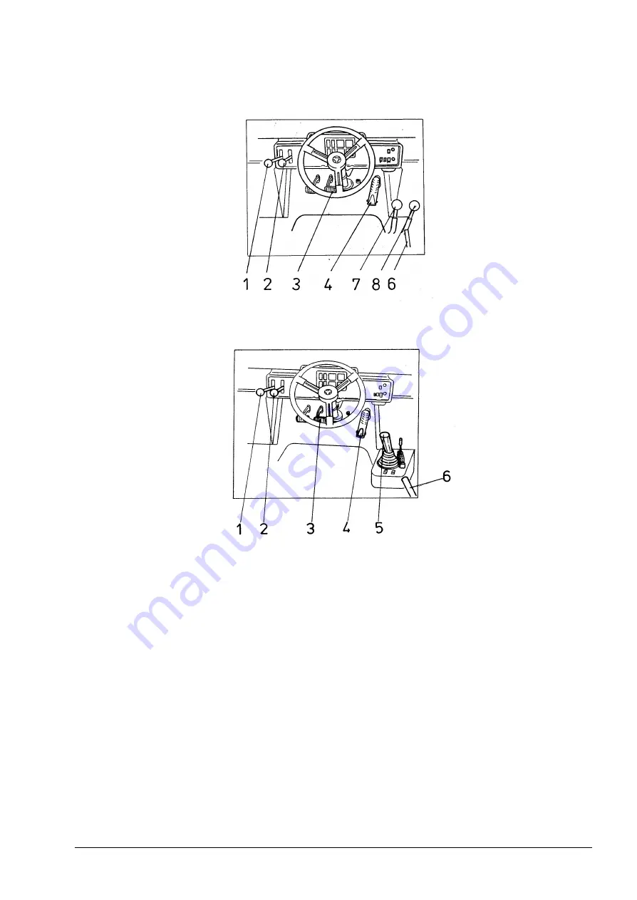
4.12. DRIVING THE MACHINE
Fig. 4.24. Driving and Stopping the Machine (Standard Version)
Fig. 4.25. Driving and Stopping the Machine (Upgraded Version)
1. Transmission Gear Range Lever
2. Transmission Direction Lever
3. Brake Pedal
4. Accelerator Pedal
5. Boom and Bucket Pilot Control Valve Lever
6. Parking Brake Lever
7. Bucket Control Lever
8. Boom Control Lever
1. Depress brake pedal (3).
2. Release parking brake lever (6).
3. Using lever (8 standard version) or lever (5 upgraded version), raise the boom until the bucket is
off the ground and in the carry position.
4. Using lever (7 standard version) or lever (5 for upgraded version), close the bucket.
5. Place transmission gear range lever (1) in the first gear position.
6. Move the transmission hinge lock plate to the right. Then place the transmission direction lever
(2) in the desired position forward or reverse.
NOTE:
If the machine is equipped with a back-up warning alarm, the alarm will sound when the
lever is placed in reverse.
7. Release brake pedal (3) and gradually depress accelerator pedal (4).
Summary of Contents for 515C
Page 3: ...OM515C520C99 1E DRESSTA ...
Page 5: ......
Page 7: ......
Page 10: ...SECTION 1 INTRODUCTION ...
Page 12: ......
Page 17: ...SECTION 2 SAFETY PRECAUTIONS ...
Page 19: ......
Page 37: ...SECTION 3 MACHINE TRANSPORT AND STORAGE ...
Page 39: ......
Page 49: ...SECTION 4 OPERATING ...
Page 51: ......
Page 107: ...SECTION 5 MAINTENANCE ...
Page 165: ...SECTION 6 SPECIFICATIONS ...
Page 167: ......
Page 181: ...SECTION 6 SPECIFICATIONS Page 16 OM515C520C99 1E DRESSTA WIRING DIAGRAMS ...
Page 182: ...SPECIFICATIONS SECTION 6 Page 17 DRESSTA OM515C520C99 1E WIRING DIAGRAMS ...
Page 187: ...SECTION 6 SPECIFICATIONS Page 22 OM515C520C99 1E DRESSTA WIRING DIAGRAMS ...


