SECTION 4
OPERATING
Page 36
OM515C520C99/1E
DRESSTA
LOADER OPERATIONS
FLOAT (UPGRADED VERSION)
When the float switch is on (Fig. 4.8), the boom will gradually lower. This position is locked with
a spring. To shift back to "hold" the switch must be put off. Use the “float" position to follow the
contour of the ground when backdragging or leveling hard ground.
WARNING! It is forbidden to lower the boom from fully raised position by moving
the control lever to “float" position. Due to weight of loader linkage it may be
dangerous for nearby personnel and damaging to the machine.
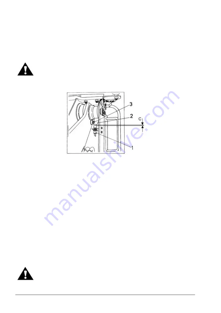
4.17.2. AUTOMATIC BOOM KICK-OUT (Fig. 4.30.)
Fig. 4.30. Automatic Boom Kick Out
1. Proximity Switch
2. Adjustment Plate
3. Locking Bolt
C. Plate-to-Switch Clearance
The electronically operated kick-out control system stops boom travel automatically at a
preselected height. This eliminates unnecessary boom travel during operation and provides for a
more efficient cycle.
Adjustment plate (2) is bolted to the left boom arm and is adjustable. Proximity switch (1) is
mounted to the front frame. Proximity switch (1) creates a magnetic field circuit which is completed
by the proximity of adjustment plate (2) within the magnetic field. Once the boom is raised to its
preselected height, adjustment plate (2) has moved out of the magnetic field, breaking the circuit.
Breaking the magnetic field circuit causes the boom control lever to move out of the detented
"RAISE" position and into the "HOLD" position, thereby stopping the travel of the boom arms. Plate-
to-switch clearance "C" necessary for the proper operation of the proximity switch is 7 to 8 [mm].
ADJUSTMENT OF AUTOMATIC BOOM KICK-OUT
To change the automatic boom kick-out position, raise the boom arms to the desired stopping
height. Place the boom control lever in the "HOLD" position. Loosen locking bolt (3) on sensor plate
(2). Move adjustment plate (2) until it is just out of the magnetic field of proximity switch (1). Tighten
locking bolt (3) on adjustment plate (2). Start the machine and test the adjustment. Repeat this
procedure until the automatic kick-out height is obtained.
WARNING! Use extra caution when adjusting loader’s bucket leveler or boom
kick-out. Use two trained people and guard against accidental movement of the
machine or loader linkage. No personnel is allowed within the reach of loader
linkage. Never work or walk under raised bucket without proper blocking.
Summary of Contents for 515C
Page 3: ...OM515C520C99 1E DRESSTA ...
Page 5: ......
Page 7: ......
Page 10: ...SECTION 1 INTRODUCTION ...
Page 12: ......
Page 17: ...SECTION 2 SAFETY PRECAUTIONS ...
Page 19: ......
Page 37: ...SECTION 3 MACHINE TRANSPORT AND STORAGE ...
Page 39: ......
Page 49: ...SECTION 4 OPERATING ...
Page 51: ......
Page 107: ...SECTION 5 MAINTENANCE ...
Page 165: ...SECTION 6 SPECIFICATIONS ...
Page 167: ......
Page 181: ...SECTION 6 SPECIFICATIONS Page 16 OM515C520C99 1E DRESSTA WIRING DIAGRAMS ...
Page 182: ...SPECIFICATIONS SECTION 6 Page 17 DRESSTA OM515C520C99 1E WIRING DIAGRAMS ...
Page 187: ...SECTION 6 SPECIFICATIONS Page 22 OM515C520C99 1E DRESSTA WIRING DIAGRAMS ...


