


SECTION 4
OPERATING
Page 56
OM515C520C99/1E
DRESSTA
QUICKCOUPLING
4.20.2. QUICKCOUPLING WITH 2-SPOOL VALVE
1. HYDRAULIC SYSTEM
The hydraulic system controls the following functions of a machine:
•
raising and lowering operations of the boom,
•
operations of the mounted equipment.
•
securing the mounted equipment on the tool carrier.
Two hydraulic hoses supplying oil to the quickcoupling cylinders are routed along the boom.
2. QUICKCOUPLING CONTROL
The quickcoupling is controlled from the operator’s cab by means of a switch controlling
a pilot solenoid valve (12, Fig. 4.2).
3. PIN LOCKING
To secure the equipment on the tool carrier (the pins in the locked position) switch the pilot solenoid
valve switch into the ON position. In this position the electric circuit controlling the mounting pin
cylinders is inactive.
4. PIN UNLOCKING
To dismount the equipment mounted on the tool carrier (the removal of the pins), place the switch
in the “OFF" position.
5. INSTALLATION OF THE EQUIPMENT
Refer to Par. 5, section 4.20.1
6. REMOVAL OF THE EQUIPMENT
Refer to Par. 6, section 4.20.1
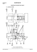
4.21. RIDE STABILIZING MECHANISM
Ride stabilizing mechanism is a hydraulic system consisting of a block of hydraulic valves and
accumulators preset for a pressure of 1.6 [MPa] (16 [bars]) (there are 5 accumulators in 515C and
6 in 520C loader). All the components are built-in in the loader’s front frame.
When a loader travels at speeds exceeding 5 [km/h] whether the bucket is empty or full, the
difference of pressure on the two sides of the boom cylinder pistons caused by unevenness of
ground causes machine pitching harmful to the operator.
The stabilizing mechanism improves machine stability, which results in:
a) greater comfort of traveling,
b) increase of traveling speed along driveways to the work area,
c) increase of travel speed with full bucket.
The stabilizing mechanism dampens machine’s pitching (the values of acceleration on the
operator’s seat can thus be reduced by half).
The RSM system is switched on automatically at a speed in excess of 5 [km/h]. The connection of
the mechanism with the hydraulic system is shown in the hydraulic schematic in Section 6.
Summary of Contents for 515C
Page 3: ...OM515C520C99 1E DRESSTA ...
Page 5: ......
Page 7: ......
Page 10: ...SECTION 1 INTRODUCTION ...
Page 12: ......
Page 17: ...SECTION 2 SAFETY PRECAUTIONS ...
Page 19: ......
Page 37: ...SECTION 3 MACHINE TRANSPORT AND STORAGE ...
Page 39: ......
Page 49: ...SECTION 4 OPERATING ...
Page 51: ......
Page 107: ...SECTION 5 MAINTENANCE ...
Page 165: ...SECTION 6 SPECIFICATIONS ...
Page 167: ......
Page 181: ...SECTION 6 SPECIFICATIONS Page 16 OM515C520C99 1E DRESSTA WIRING DIAGRAMS ...
Page 182: ...SPECIFICATIONS SECTION 6 Page 17 DRESSTA OM515C520C99 1E WIRING DIAGRAMS ...
Page 187: ...SECTION 6 SPECIFICATIONS Page 22 OM515C520C99 1E DRESSTA WIRING DIAGRAMS ...


