


MAINTENANCE
SECTION 5
Page 29
DRESSTA
OM515C520C99/1E
5.10. ELECTRICAL SYSTEM
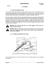
5.10.1. ELECTRIC WIRES
WARNING! Before working on the electric system, disconnect the master
electrical switch and remove the key.
All terminals must be clean and fastened securely. Repair or replace all broken wires immediately.
Surface under all terminals must be clean and good electrical connections must be established
after reassembly. Also all clips must grip cables tightly to prevent vibrations and rapid cable wear.
All clips and straps must be closed in a workmanlike manner, so as not to damage the insulation.
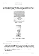
5.10.2. CIRCUIT BREAKERS
AUTOMATIC CIRCUIT BREAKERS
Electrical circuits are protected by automatic reset circuit breakers. They are located under the
instrument panel. In the event of a "short circuit" or "ground", the circuit breaker will open before
damage occurs and will continue to open and close until the trouble clears or is corrected. When
replacing use circuit breakers of the same amps.
To replace circuit breaker carry out as follows:
1. Remove two screws and lock washers securing the breaker to the instrument panel.
2. Remove the circuit breaker and replace it.
3. Reassembly in the reverse order.
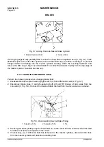
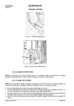
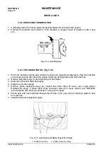
5.10.3. BULB OR LAMP REPLACEMENT
FRONT AND REAR ROAD LIGHTS
Remove the sealed beam unit and replace the bulb with a new one.
STOP AND PARKING LIGHTS
Raise the rubber retainer lip and remove the sealed beam or the bulb depending on the type of
lamp. Install a new sealed beam or bulb of the same type.
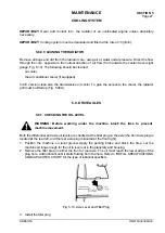
INSTUMENT PANEL LIGHTS
Reach under the instrument panel and turn the bulb holder. Pull the holder free. Press down on the
bulb in the holder, turn counterclockwise and pull it free of the socket. Replace with a bulb of the
same type. Place a new bulb into the holder, press down and turn clockwise. Insert the holder into
the instrument panel and turn until secure.
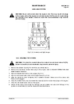
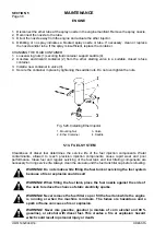
5.10.4. BATTERIES
A loader is equipped with two twelve volt maintenance free batteries. They are located in the battery
compartment on the left-hand side of the rear main frame. (In CE version they are located in the
counterweight recess).
Never allow the battery to stand on concrete, ground or a metal support unless proper insulation is
provided. A wooden platform or board is sufficient insulation. Be sure the battery is fastened
securely to avoid damage from vibration.
Summary of Contents for 515C
Page 3: ...OM515C520C99 1E DRESSTA ...
Page 5: ......
Page 7: ......
Page 10: ...SECTION 1 INTRODUCTION ...
Page 12: ......
Page 17: ...SECTION 2 SAFETY PRECAUTIONS ...
Page 19: ......
Page 37: ...SECTION 3 MACHINE TRANSPORT AND STORAGE ...
Page 39: ......
Page 49: ...SECTION 4 OPERATING ...
Page 51: ......
Page 107: ...SECTION 5 MAINTENANCE ...
Page 165: ...SECTION 6 SPECIFICATIONS ...
Page 167: ......
Page 181: ...SECTION 6 SPECIFICATIONS Page 16 OM515C520C99 1E DRESSTA WIRING DIAGRAMS ...
Page 182: ...SPECIFICATIONS SECTION 6 Page 17 DRESSTA OM515C520C99 1E WIRING DIAGRAMS ...
Page 187: ...SECTION 6 SPECIFICATIONS Page 22 OM515C520C99 1E DRESSTA WIRING DIAGRAMS ...


