SECTION 5
MAINTENANCE
Page 56
OM515C520C99/1E
DRESSTA
LOADER EQUIPMENT
5. Protect disassembled O-rings (3) and 1.5 [mm] shims (4) per drawing 429-17-1006 and
shim (5) per drawing 429-17-1005.
6. Reinstall the bucket in the reverse order.
IMPORTANT:
Allowable gap between bucket supports and boom arms is 1.5 [mm]. If gaps are
bigger, fill symmetrically with shims.
WARNING! When replacing the bucket, take care. Disassembled heavy compo-
nents of loader linkage system (boom arms, bellcrank) must be securely
protected against sudden movement.
5.22. AIR CONDITIONER OR HEATER (IF EQUIPPED)
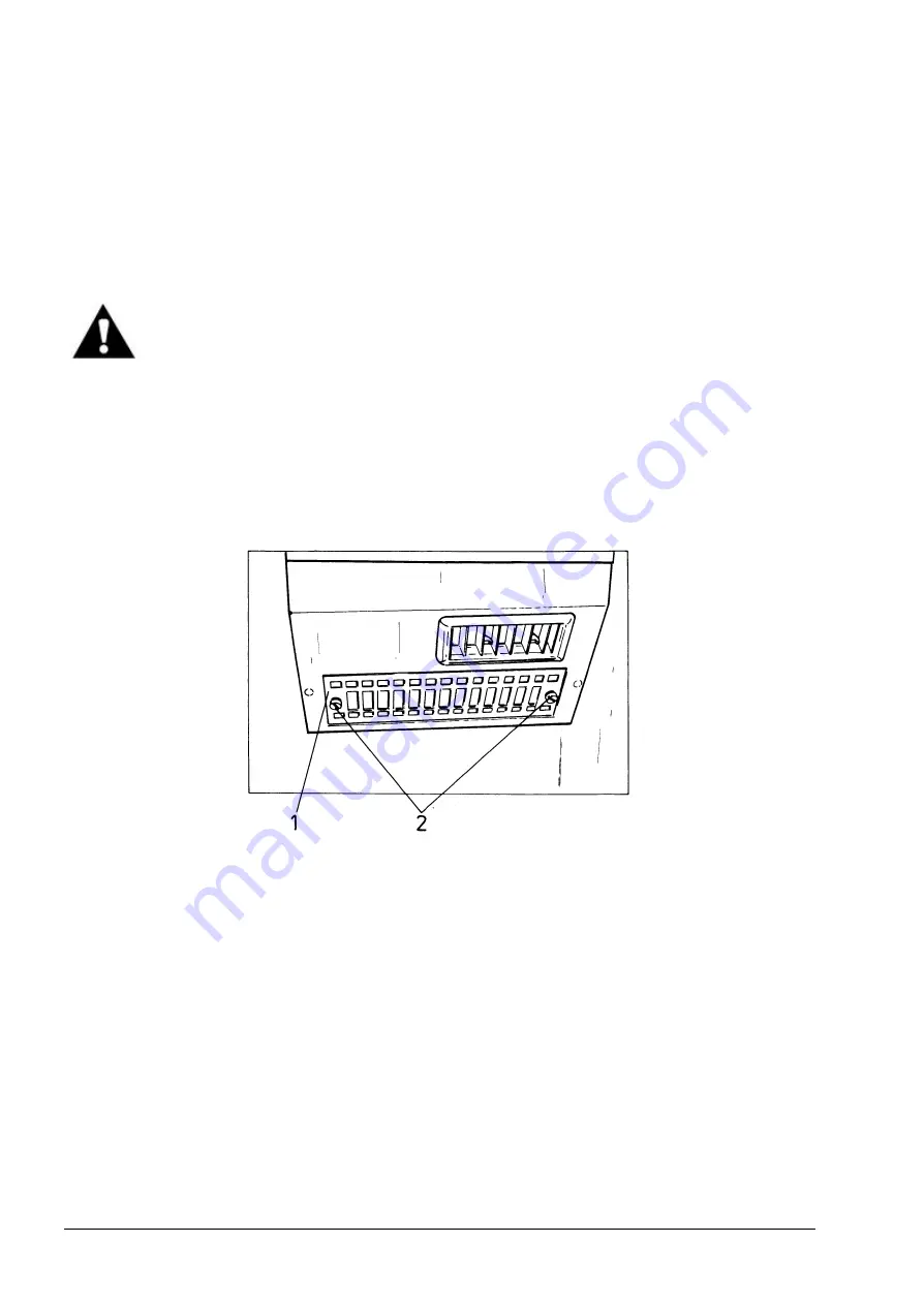
5.22.1. INSIDE FILTER (Fig. 5.50)
Fig. 5.50. Inside Filter
1. Filter Cover 2. Screw
A filter inside the console cleans the air as it is recirculated. The filter should be changed
periodically.
1. Remove cover (1) by turning thumb screws.
2. Remove the filter from the cover.
3. Wash the filter in warm water with a small amount of nonsudsing detergent. Rinse the filter in
clean water and dry it thoroughly.
4. Reinstall the filter in the housing and reinstall the cover.
Summary of Contents for 515C
Page 3: ...OM515C520C99 1E DRESSTA ...
Page 5: ......
Page 7: ......
Page 10: ...SECTION 1 INTRODUCTION ...
Page 12: ......
Page 17: ...SECTION 2 SAFETY PRECAUTIONS ...
Page 19: ......
Page 37: ...SECTION 3 MACHINE TRANSPORT AND STORAGE ...
Page 39: ......
Page 49: ...SECTION 4 OPERATING ...
Page 51: ......
Page 107: ...SECTION 5 MAINTENANCE ...
Page 165: ...SECTION 6 SPECIFICATIONS ...
Page 167: ......
Page 181: ...SECTION 6 SPECIFICATIONS Page 16 OM515C520C99 1E DRESSTA WIRING DIAGRAMS ...
Page 182: ...SPECIFICATIONS SECTION 6 Page 17 DRESSTA OM515C520C99 1E WIRING DIAGRAMS ...
Page 187: ...SECTION 6 SPECIFICATIONS Page 22 OM515C520C99 1E DRESSTA WIRING DIAGRAMS ...


