SECTION 6
SPECIFICATIONS
Page 32
OM515C520C99/1E
DRESSTA
6.9. 515C AND 520C LOADERS EQUIPMENT
The following equipment can be mounted on a loader instead of the standard bucket:
6.9.1. QUICKCOUPLING
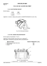
The loader can be equipped with a quickcoupling designed for quick installation and removal of
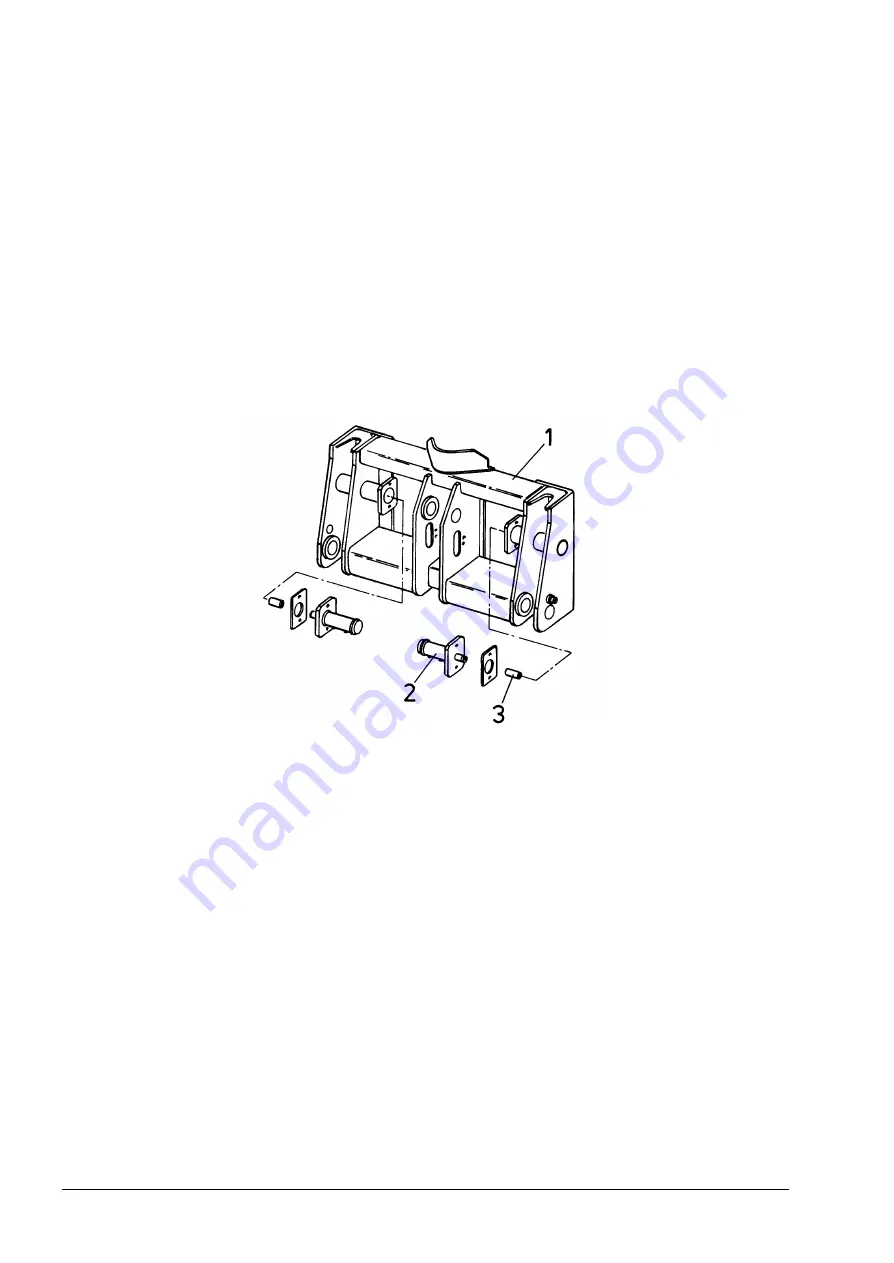
optional equipment (bucket, forklift, dozer blade). The quickcoupling (Fig. 6.11) consists of
a welded tool carrier fitted with two cylinders operating two pins locking the equipment on the tool
carrier. The tool carrier is fastened on the boom with mounting pins. The quickcoupling cylinders
are controlled from the operator’s compartment (refer to QUICKCOUPLING, Section 4.20). Before
operating any mounted equipment make sure it has been fastened securely and that the locking
pins have slid into the matching holes.
Fig. 6.11. Quickcoupling
1. Tool Carrier 2. Hydraulic Cylinder 3. Locking Pin
6.9.2. BUCKETS FOR QUICKCOUPLING
The following are the buckets designed for installation on the tool carrier, their capacities and
application:
515C
520C
Bucket capacity [m
3
]
Soil density [kg/m
3
]
Bucket capacity [m
3
] Soil density [kg/m
3
]
1.05
2000 and less
1.72
1800 and less
1.24
1800 and less
1.91
1600 and less
1.44
1600 and less
2.10
1400 and less
1.53
1500 and less
1.62
1400 and less
Summary of Contents for 515C
Page 3: ...OM515C520C99 1E DRESSTA ...
Page 5: ......
Page 7: ......
Page 10: ...SECTION 1 INTRODUCTION ...
Page 12: ......
Page 17: ...SECTION 2 SAFETY PRECAUTIONS ...
Page 19: ......
Page 37: ...SECTION 3 MACHINE TRANSPORT AND STORAGE ...
Page 39: ......
Page 49: ...SECTION 4 OPERATING ...
Page 51: ......
Page 107: ...SECTION 5 MAINTENANCE ...
Page 165: ...SECTION 6 SPECIFICATIONS ...
Page 167: ......
Page 181: ...SECTION 6 SPECIFICATIONS Page 16 OM515C520C99 1E DRESSTA WIRING DIAGRAMS ...
Page 182: ...SPECIFICATIONS SECTION 6 Page 17 DRESSTA OM515C520C99 1E WIRING DIAGRAMS ...
Page 187: ...SECTION 6 SPECIFICATIONS Page 22 OM515C520C99 1E DRESSTA WIRING DIAGRAMS ...


