SECTION 6
SPECIFICATIONS
Page 36
OM515C520C99/1E
DRESSTA
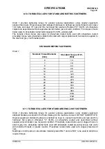
TORQUE VALUES FOR STANDARD ENGLISH FASTENERS
Chart 2
Nominal Thread Diameter
[inch]
Standard Torque
±±
10%
[Nm]
1/4
10
5/16
21
3/8
38
7/16
60
1/2
92
9/16
130
5/8
180
3/4
325
7/8
520
1
780
1 - 1/8
1110
1 - 1/4
1565
1 - 3/8
2050
1 - 1/2
2720
1 - 3/4
3380
2
5080
6.12. TORQUE VALUES FOR SPLIT FLANGE CONNECTIONS
The following chart 3 provides the tightening torques for split flange connections used in hydraulic
systems. Split flanges and fitting shoulders should fit squarely. Install all bolts, finger tighten and
then torque evenly. Overtorquing bolts will damage the flanges and/or bolts, which may cause
leakage.
Chart 3
Bolt size in inches
Flange size in inches*
Torque Value [Nm]
1/2
5/16
20 – 24
3/4
3/8
30 – 37
1
3/8
37 – 47
1 – 1/4
7/16
47 – 61
1 – 1/2
1/ 2
62 – 79
2
1/ 2
75 – 88
2 – 1/2
1/ 2
107 – 123
3
5/8
187 – 203
3 – 1/2
5/8
159 – 180
*
)
Inside diameter of hydraulic tube or hose fitting.
Summary of Contents for 515C
Page 3: ...OM515C520C99 1E DRESSTA ...
Page 5: ......
Page 7: ......
Page 10: ...SECTION 1 INTRODUCTION ...
Page 12: ......
Page 17: ...SECTION 2 SAFETY PRECAUTIONS ...
Page 19: ......
Page 37: ...SECTION 3 MACHINE TRANSPORT AND STORAGE ...
Page 39: ......
Page 49: ...SECTION 4 OPERATING ...
Page 51: ......
Page 107: ...SECTION 5 MAINTENANCE ...
Page 165: ...SECTION 6 SPECIFICATIONS ...
Page 167: ......
Page 181: ...SECTION 6 SPECIFICATIONS Page 16 OM515C520C99 1E DRESSTA WIRING DIAGRAMS ...
Page 182: ...SPECIFICATIONS SECTION 6 Page 17 DRESSTA OM515C520C99 1E WIRING DIAGRAMS ...
Page 187: ...SECTION 6 SPECIFICATIONS Page 22 OM515C520C99 1E DRESSTA WIRING DIAGRAMS ...


