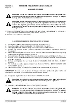
MACHINE TRANSPORT AND STORAGE
SECTION 3
Page 3
DRESSTA
OM515C520C99/1E
3.1. MACHINE TRANSPORT
3.1.1. GENERAL
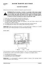
WARNING! During transportation of a machine the front and rear frame should be
blocked by means of a special locking bar and interlocking pins.
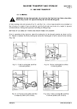
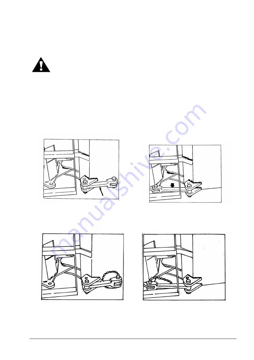
A frame locking bar and two pins (Fig. 3.1 and Fig. 3.2) - in the stowed position are provided on
the LH side of a loader. They are used to lock the front and rear frame of a loader to prevent
accidental frame turning during service and lifting on lifting slings.
METHOD OF LOCKING OF FRONT AND REAR FRAME OF LOADER
Prior to operating of the machine, place the locking bar in the stowed position as shown in Fig.
3.1. Repair or replace the frame locking bar and pins if damaged or lost to ensure frame locking,
(Fig. 3.2).
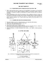
Fig. 3.1. Frame Locking Bar and Pins
in stowed position
Fig. 3.2. Frame Locking Bar and Pins
in locked position
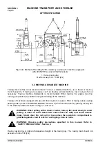
Fig. 3.1.A. Frame Locking Bar and Pins
in stowed position (CE version)
Fig. 3.2.A. Frame Locking Bar and Pins
in locked position (CE version)
Summary of Contents for 515C
Page 3: ...OM515C520C99 1E DRESSTA ...
Page 5: ......
Page 7: ......
Page 10: ...SECTION 1 INTRODUCTION ...
Page 12: ......
Page 17: ...SECTION 2 SAFETY PRECAUTIONS ...
Page 19: ......
Page 37: ...SECTION 3 MACHINE TRANSPORT AND STORAGE ...
Page 39: ......
Page 49: ...SECTION 4 OPERATING ...
Page 51: ......
Page 107: ...SECTION 5 MAINTENANCE ...
Page 165: ...SECTION 6 SPECIFICATIONS ...
Page 167: ......
Page 181: ...SECTION 6 SPECIFICATIONS Page 16 OM515C520C99 1E DRESSTA WIRING DIAGRAMS ...
Page 182: ...SPECIFICATIONS SECTION 6 Page 17 DRESSTA OM515C520C99 1E WIRING DIAGRAMS ...
Page 187: ...SECTION 6 SPECIFICATIONS Page 22 OM515C520C99 1E DRESSTA WIRING DIAGRAMS ...


