OPERATING
SECTION 4
Page 27
DRESSTA
OM515C520C99/1E
4.8. AIR CLEANER SERVICE INDICATOR
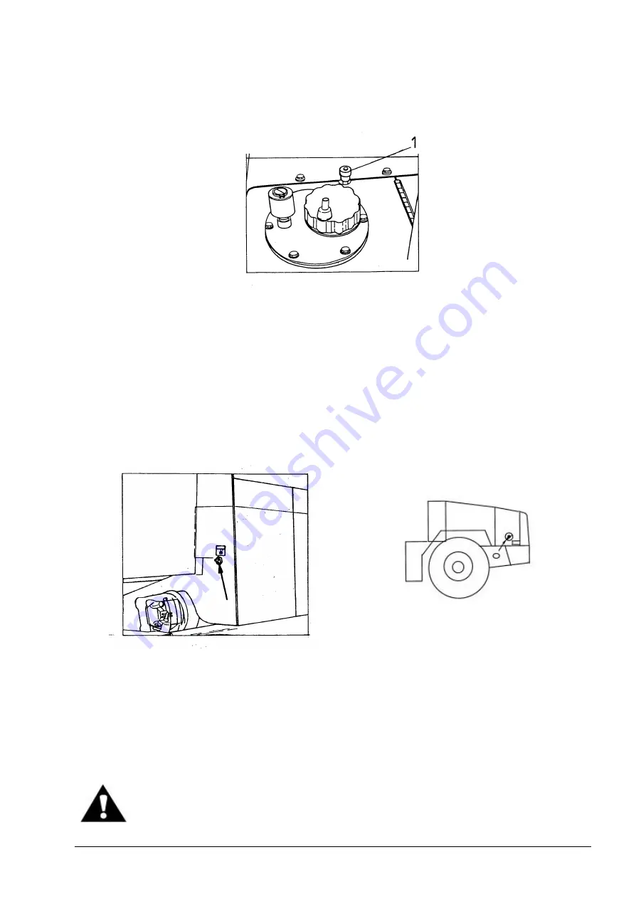
Fig. 4.21. Service Indicator
1. Service Indicator
The indicator is located in the upper front part of the hydraulic reservoir (behind the cab). During
operation, the red band will gradually rise in the indicator window as dirt accumulates in the air filter
elements. When the filter elements reach the maximum allowable restriction, the red band will
completely fill the indicator window and automatically lock in this position. The red band will remain
fully exposed even after stopping the engine. When this happens, filter element service is required.
Press the reset button on top of indicator after the elements have been serviced.
4.9. ELECTRIC SYSTEM MASTER SWITCH
Fig. 4.22. Electric System Master Switch
Fig. 4.22A. Electric System Master Switch
(CE Version)
The switch is located on the LH side of the hydraulic tank behind the cab and is connected in series
between the battery positive terminal (+) and receivers, thus turning "ON" or "OFF" battery voltage
to all electric systems. The master switch must always be turned to the "ON" position when the
engine is running to prevent any damage to the alternator and/or electric system. On machines in
CE version the switch is located at the back on the left hand side.
WARNING: Before servicing the machine, turn off the electric system master
switch and remove the key. Tag the machine to warn against starting the engine.
Summary of Contents for 515C
Page 3: ...OM515C520C99 1E DRESSTA ...
Page 5: ......
Page 7: ......
Page 10: ...SECTION 1 INTRODUCTION ...
Page 12: ......
Page 17: ...SECTION 2 SAFETY PRECAUTIONS ...
Page 19: ......
Page 37: ...SECTION 3 MACHINE TRANSPORT AND STORAGE ...
Page 39: ......
Page 49: ...SECTION 4 OPERATING ...
Page 51: ......
Page 107: ...SECTION 5 MAINTENANCE ...
Page 165: ...SECTION 6 SPECIFICATIONS ...
Page 167: ......
Page 181: ...SECTION 6 SPECIFICATIONS Page 16 OM515C520C99 1E DRESSTA WIRING DIAGRAMS ...
Page 182: ...SPECIFICATIONS SECTION 6 Page 17 DRESSTA OM515C520C99 1E WIRING DIAGRAMS ...
Page 187: ...SECTION 6 SPECIFICATIONS Page 22 OM515C520C99 1E DRESSTA WIRING DIAGRAMS ...


