MAINTENANCE
SECTION 5
Page 19
DRESSTA
OM560C99/1E
AIR CLEANING SYSTEM
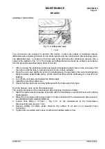
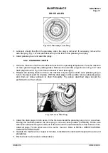
indicated by a loss of indicator operation and can be checked as follows: Remove the pre-cleaner
hood 12, Fig. 5.9. Start the engine and operate at low idle. Gradually seal off the air intake opening
with a flat piece of cardboard until it is almost completely covered. If the red signal band of the
indicator fails to rise and lock in position, the service indicator orifice is plugged. Once detected , the
leak must be located and corrected immediately and service indicator orifice fitting cleaned or
replaced to regain the full advantage of the service indicator.
Service the indicator orifice fitting as follows:
1. Disconnect the indicator tube from orifice fitting at the air cleaner elbow.
2. Remove the orifice fitting from the air cleaner elbow.
3. Wash the orifice in solvent and blow with compressed air. Clean the orifice opening with wire in
the direction opposite to the air flow, if necessary.
4. Install the orifice fitting and service indicator.
5.6.5. PRECLEANER HOOD
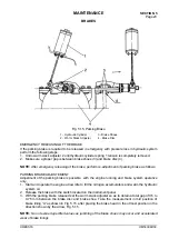
The dome of the precleaner hood 12, Fig. 5.9. serves as a rain shield and the screen prevents chaff
and course dirt from getting into the air cleaner. Keep this screen clean from all chaff, oil or dust.
Clogged holes in the screen will reduce the power of the engine by restricting the flow of air. Loosen
clamp screw 11 on the precleaner hood. Twist and pull upward to remove the cap. Use
compressed air to clean the screen. If compressed air is not available, wash in clean hot water or
water containing a small amount of nonsudsing detergent.
CAUTION: Never wash precleaner installed on the machine as water may
penetrate to the engine.
5.7. BRAKES
5.7.1. SERVICE BRAKE SYSTEM
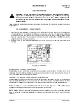
A wheel loader is equipped with “wet” brakes inboard mounted close to the planetaries of the drive
axles. They do not require servicing during the operation of a machine. The brake system is
supplied with a multi-piston pump with output compensation driven directly from the engine (engine
mounted). The brake cooling is secured by a separate cooling system supplied by a gear pump
(driven from the torque converter). Both systems and drive system of the machine operate in one
hydraulic system, with common oil reservoir in transmission. The brake system is equipped with
hydraulic accumulators protecting emergency braking if the engine fails to operate.
WARNING! The brake system pump is driven directly by the engine. The brake
system is inoperative with the engine stopped. The hydraulic accumulators
secure emergency braking only.
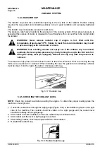
The service brake system is divided into two separate circuits:
−
front wheels brake circuit,
−
rear wheels brake circuit.
These circuits can operate independently securing safe operation of a wheel loader. The service
brake is actuated with the brake pedal from the operator’s cab. Increasing gradually pressure
exerted on the brake pedal the required braking effect is obtained. The more the pedal is depressed
the stronger the braking effect.
Summary of Contents for 560C
Page 1: ...OM560C99 1E OPERATOR S MANUAL 560C SERIAL NUMBERS 15001 AND UP ...
Page 3: ......
Page 5: ......
Page 7: ......
Page 10: ...SECTION 1 INTRODUCTION ...
Page 12: ......
Page 16: ...SECTION 2 SAFETY PRECAUTIONS ...
Page 18: ......
Page 32: ...SECTION 3 MACHINE TRANSPORT AND STORAGE ...
Page 34: ......
Page 42: ...SECTION 4 OPERATING ...
Page 43: ......
Page 45: ......
Page 49: ...SECTION 4 OPERATING Page 6 OM560C99 1E DRESSTA UNIVERSAL SYMBOLS FOR INSTRUMENTS AND CONTROLS ...
Page 88: ...SECTION 5 MAINTENANCE ...
Page 141: ...SECTION 6 SPECIFICATIONS ...
Page 143: ......

