


SPECIFICATIONS
SECTION 6
Page 9
DRESSTA
OM560C99/1E
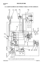
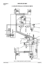
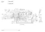
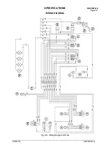
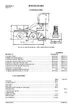
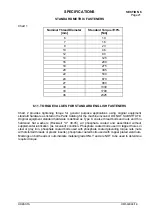
BRAKE HYDRAULIC SYSTEM SCHEMATIC
The description of the assemblies shown in schematic, Fig. 6.4.:
1. Cooling Pump
2. Brake Pump
3. Cooling Filter
4. Regulating Valve
5. Nitrogen Accumulator
6. Brake Valve (Brake Pedal)
7. Parking Brake Solenoid Valve
8. Parking Brake Hydraulic Cylinder
9. Differential Valve
10. Cooling System Low Pressure Switch
11. Valve Block
12. Transmission Disconnect Solenoid Valve
13. Parking Brake Warning Light Switch
14. Suction Strainer
15. Wheel Brake Assembly
16. Wheel Brake Piston
17. Supply From Transmission System
18. Transmission Oil Reservoir
19.
Supply of Transmission Disconnect Valve
Summary of Contents for 560C
Page 1: ...OM560C99 1E OPERATOR S MANUAL 560C SERIAL NUMBERS 15001 AND UP ...
Page 3: ......
Page 5: ......
Page 7: ......
Page 10: ...SECTION 1 INTRODUCTION ...
Page 12: ......
Page 16: ...SECTION 2 SAFETY PRECAUTIONS ...
Page 18: ......
Page 32: ...SECTION 3 MACHINE TRANSPORT AND STORAGE ...
Page 34: ......
Page 42: ...SECTION 4 OPERATING ...
Page 43: ......
Page 45: ......
Page 49: ...SECTION 4 OPERATING Page 6 OM560C99 1E DRESSTA UNIVERSAL SYMBOLS FOR INSTRUMENTS AND CONTROLS ...
Page 88: ...SECTION 5 MAINTENANCE ...
Page 141: ...SECTION 6 SPECIFICATIONS ...
Page 143: ......


