SPECIFICATIONS
SECTION 6
Page 11
DRESSTA
OM560C99/1E
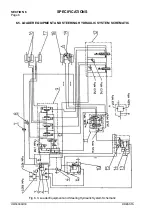
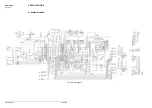
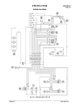
WIRING DIAGRAM
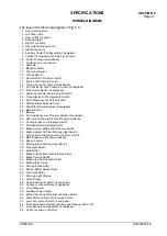
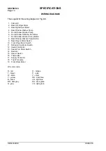
The legend for the wiring diagram in Fig. 6.5.:
1. Rear Parking Lamp
2. Left Stop Lamp
3. Rear Left Work Lamp
4. Back-up Alarm
5. Right Work Lamp
6. Rear Right Parking Lamp
7. Right Stop Lamp
8. Auxiliary Cooler Fan Assembly (if equipped)
9. Coolant Temperature Warning Light Switch
10. Coolant Temperature Sensor
11. Coolant Low Level Sensor
12. Alternator
13. Magnetic Switch
14. Fuel Level Sensor
15. Cranking Motor
16. Hourmeter Oil Pressure Switch
17. Engine Oil Pressure Sensor
18. Torque Converter Temperature Sensor
19. Air Conditioner High Pressure Switch (if equipped)
20. Tachometer Sensor (if equipped)
21. Hydraulic Oil Filter Warning Light Switch
22. Transmission Oil Temperature Switch
23. Drive Disconnection Solenoid Valve
24. Parking Brake Solenoid Valve
25. Start Ether Solenoid Valve (if equipped)
26. Master Switch
27. Battery
28. Air Conditioner Low Pressure Switch (if equipped)
29. Hydraulic Accumulators Gas Pressure Switches
30. Cooling Brake Low Pressure Switch
31. Directional Neutral Safety Switch
32. Brake System Differential Pressure Switch
33. Brake System Oil Filter Warning Light Switch
34. Ground Drive Steering Alarm and Lamp Switch
35. Main Brake Low Pressure Switches
36. Back-up Alarm
37. Parking Brake Warning Light Switch
38. Stop Light Switch
39. Horn Button
40. Brake Differential Pressure Delay Relay
41. Brake Parking Switch
42. Brake Alarm Elimination Switch
43. Brake Alarm Relay
44. Parking Brake Relay
45. Neutral Safety Switch Relay
46. Stop Light Relay
47. Warning Light Diodes
48. Alarm Diodes
49. Directional Signal Switch (if equipped)
50. Cooling Low Level Relay (if equipped)
51. Circuit Breakers
52. Auxiliary Power Supply
53. Bulbs Check and Drive Disconnection Switch
54. Ether Start and Rear Work Lamps Switch
55. Low Level Lamps Switch (if equipped)
56. Front Work Lamps Switch (Parking and Passing, 560C CE)
57. Front Auxiliary Lamps Switch (if equipped)
58. Cab Work Lamp Connector
Summary of Contents for 560C
Page 1: ...OM560C99 1E OPERATOR S MANUAL 560C SERIAL NUMBERS 15001 AND UP ...
Page 3: ......
Page 5: ......
Page 7: ......
Page 10: ...SECTION 1 INTRODUCTION ...
Page 12: ......
Page 16: ...SECTION 2 SAFETY PRECAUTIONS ...
Page 18: ......
Page 32: ...SECTION 3 MACHINE TRANSPORT AND STORAGE ...
Page 34: ......
Page 42: ...SECTION 4 OPERATING ...
Page 43: ......
Page 45: ......
Page 49: ...SECTION 4 OPERATING Page 6 OM560C99 1E DRESSTA UNIVERSAL SYMBOLS FOR INSTRUMENTS AND CONTROLS ...
Page 88: ...SECTION 5 MAINTENANCE ...
Page 141: ...SECTION 6 SPECIFICATIONS ...
Page 143: ......


