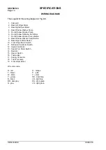
SPECIFICATIONS
SECTION 6
Page 15
DRESSTA
OM560C99/1E
6.8. SPECIFICATIONS
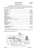
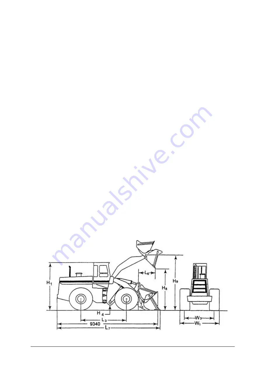
6.8.1. GENERAL SPECIFICATIONS OF THE LOADER (Refer to Fig. 6.7. and 6.8.)
Below specified specifications are for standard configuration of 560C wheel loader equipped with
ROPS-FOPS cab, standard bucket, counterweight and 29.5 x 29 tires.
Rated bucket capacity................................................................................................................ 5.73m
3
Bucket width ............................................................................................................................3645 mm
Dump clearance – H
8
*
)
...........................................................................................................3630 mm
Reach L
6
..................................................................................................................................1470 mm
Dump height – H
9
....................................................................................................................4110 mm
Breakout force..........................................................................................................................310.5 kN
Static tipping load **
)
•
straight ....................................................................................................................................282 kN
•
full turn .................................................................................................................................250.6 kN
Operating weight ..................................................................................................................... 41800 kg
Load capacity [kN]
±
10%.............................................................................................................. 125.3
Overall length with bucket L
7
...................................................................................................9520 mm
Turning radius, outside corner of bucket @ carry..................................................................8600 mm
Articulation .........................................................................................................................................35
°
Tread - W
3
...............................................................................................................................2590 mm
Wheelbase - L
3
........................................................................................................................3940 mm
Height to the top of cab – H
1
....................................................................................................4110 mm
Ground clearance – H
4
..............................................................................................................500 mm
Machine width – W
1
.................................................................................................................3380 mm
Axle oscillation ...............................................................................................................................11.5
°
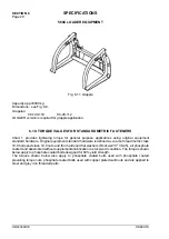
Operating weight, LOGGER version
•
Grapple 90-108-119............................................................................................................ 50011 kg
•
Grapple HC-90-112............................................................................................................. 50478 kg
*
)
increases or decreases according to the tire size
**
)
machine stability, weight and performance are affected by the machine configuration and optional equipment
NOTE:
Performance specified per SAE J732.
Fig. 6.7. Overall Dimensions – Wheel Loader 560C
Summary of Contents for 560C
Page 1: ...OM560C99 1E OPERATOR S MANUAL 560C SERIAL NUMBERS 15001 AND UP ...
Page 3: ......
Page 5: ......
Page 7: ......
Page 10: ...SECTION 1 INTRODUCTION ...
Page 12: ......
Page 16: ...SECTION 2 SAFETY PRECAUTIONS ...
Page 18: ......
Page 32: ...SECTION 3 MACHINE TRANSPORT AND STORAGE ...
Page 34: ......
Page 42: ...SECTION 4 OPERATING ...
Page 43: ......
Page 45: ......
Page 49: ...SECTION 4 OPERATING Page 6 OM560C99 1E DRESSTA UNIVERSAL SYMBOLS FOR INSTRUMENTS AND CONTROLS ...
Page 88: ...SECTION 5 MAINTENANCE ...
Page 141: ...SECTION 6 SPECIFICATIONS ...
Page 143: ......


