SECTION 4
OPERATING
Page 14
OM560C99/1E
DRESSTA
INSTRUMENTS AND CONTROLS
CAUTION: DO NOT use the ether injector when air temperature is above
freezing (0
°°
). Follow the correct method for starting the engine. Refer to
Section 5 ETHER INJECTOR.
22.
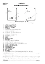
TRANSMISSION DISCONNECT/BULB CHECK SWITCH
Used for selection method of braking and to check that instrument and warning lights are working. It
has three positions:
−
braking with transmission connected,
−
braking with transmission disconnected,
−
warning and illumination lights check (lower position).
Before operating the machine the operator should check that instrument and warning lights are
working, i.e. bulbs are not burnt or bulb circuits broken. Therefore, before starting operation move
the switch in down position for 2 to 3 seconds. Additional information on using the switch, see
Section 5 SERVICE BRAKES.
23. ECM FAULT CODE DISPLAY SWITCH
This switch has three positions. The upper and lower position enables to display successive fault
codes. The switch automatically returns to the central position.
24. ECM MEMORY SWITCH
The switch can be placed in two positions: the upper position (normal), the lower position fault
memory (memory on)
ECM registers all abnormal engine and its systems parameters (high temperature of coolant, low
coolant level, low oil pressure, etc)
Active faults (persisting) may be displayed using lights 25,26,27. Inactive faults (instantaneous) may
be read using computer.
25. WARNING LIGHT (RED)
This light indicates serious malfunction of the engine. Stop the engine immediately, or the engine
will be stopped by ECM module.
26. WARNING LIGHT (YELLOW)
This light indicates minor malfunction of the engine, the engine can still be operated but for its
protection ECM may reduce some parameters (power, rpm). The failure
must be repaired as soon
as possible.
27. WARNING LIGHT (ORANGE)
The light indicates low coolant level. Low coolant level results in deterioration of some parameters
resulting in stopping the engine.
NOTE:
The engine protection system records separate fault codes when an out-of-range condition
is found for any of the sensors in the engine protection system. (Coolant temperature, coolant level,
oil temperature, and oil pressure - Refer to the "ENGINE OPERATOR'S MANUAL" for more
information).
28. PARKING BRAKE KNOB
This knob applies and releases the parking brake. Pull the knob to apply the parking brake. The
parking brake is released with hydraulic cylinder supplied from the brake system. The brake is
spring applied. In case of pressure loss the brake release with this knob is not possible. For the
method of emergency brake release see Section 5 PARKING BRAKE . The parking brake warning
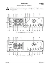
light 7 Fig. 4.2 and 4.3 will light and alarm is activated when the brake is applied.
NOTE:
Before moving the machine release the parking brake.
Summary of Contents for 560C
Page 1: ...OM560C99 1E OPERATOR S MANUAL 560C SERIAL NUMBERS 15001 AND UP ...
Page 3: ......
Page 5: ......
Page 7: ......
Page 10: ...SECTION 1 INTRODUCTION ...
Page 12: ......
Page 16: ...SECTION 2 SAFETY PRECAUTIONS ...
Page 18: ......
Page 32: ...SECTION 3 MACHINE TRANSPORT AND STORAGE ...
Page 34: ......
Page 42: ...SECTION 4 OPERATING ...
Page 43: ......
Page 45: ......
Page 49: ...SECTION 4 OPERATING Page 6 OM560C99 1E DRESSTA UNIVERSAL SYMBOLS FOR INSTRUMENTS AND CONTROLS ...
Page 88: ...SECTION 5 MAINTENANCE ...
Page 141: ...SECTION 6 SPECIFICATIONS ...
Page 143: ......


