OPERATING
SECTION 4
Page 27
DRESSTA
OM560C99/1E
STARTING AND STOPPING THE ENGINE
If a malfunction is found by ECM in the system (sender malfunction, low oil pressure, low
coolant level, etc) it is stored in memory as active malfunction.
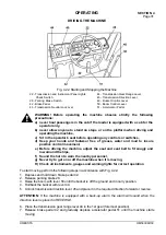
To read active malfunction codes turn the ignition key to the OFF position, place switch 24 in
CHECK top position, then turn the ignition key to the RUN position.
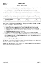
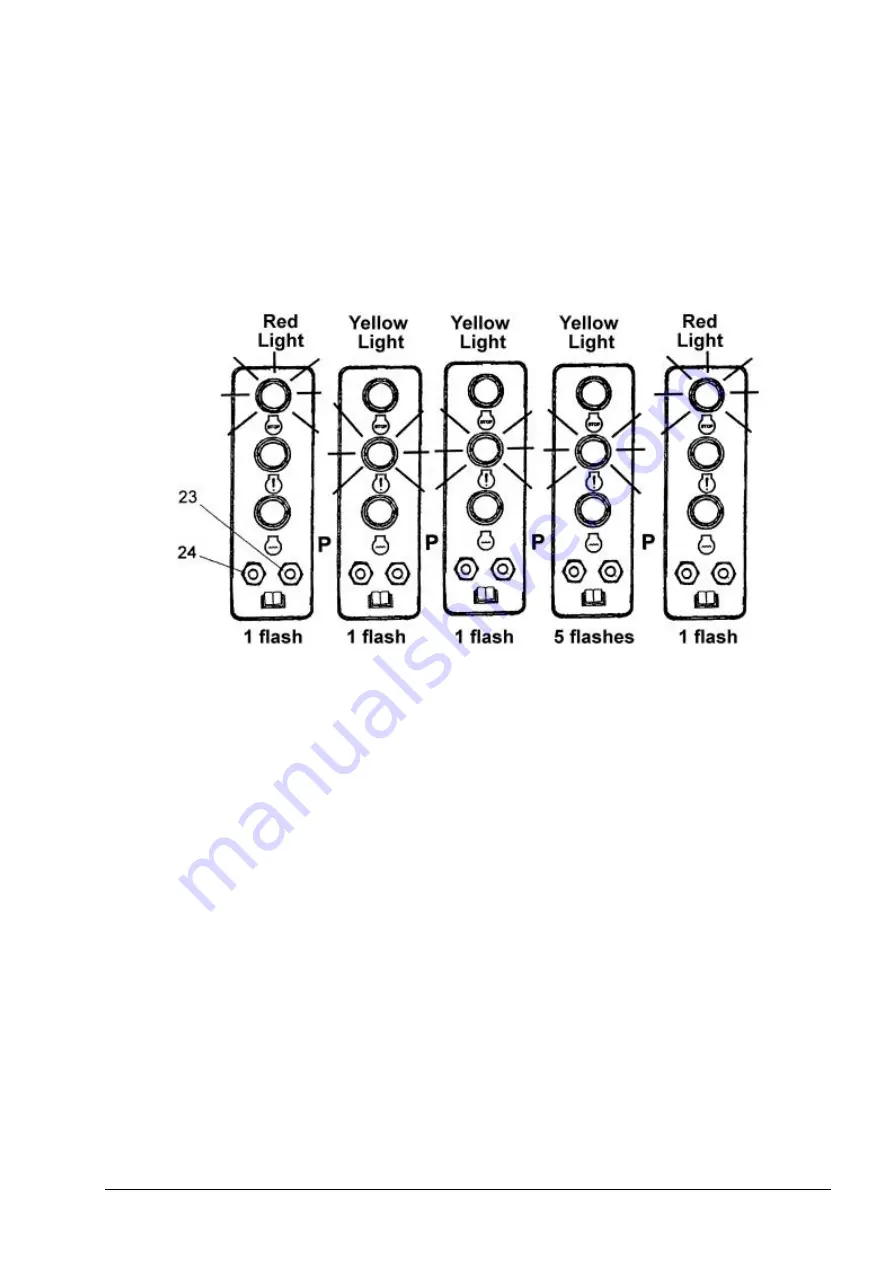
Place 23 SELECT switch in top or bottom position. In this position the malfunction code is
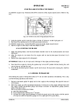
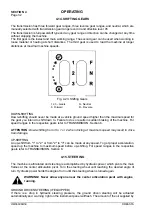
displayed, Fig. 4.20.
Exemplary malfunction code displayed:
Fig. 4.20. Malfunction Code Displayed
P - 1 Second Pause
23 - Engine Malfunction Code Switch Stored In ECM Memory
24 - ECM Memory Activation Switch
Malfunction code 115 – engine speed sender
For the list of malfunction codes – see ENGINE MANUAL
If any active malfunctions are found contact Construction Equipment Authorized Distributor.
7. Keep the key till the engine starts but no longer than 30 seconds. Then release the key
immediately, it returns automatically to the RUN position.
ATTENTION:
To prevent damage to the cranking motor and avoid low battery output, do not
continuously crank engine for more than 30 seconds. Allow a recovery period of 2 minutes between
crankings.
ATTENTION:
Never start the engine indoors unless proper exhaust ventilation is provided to
remove deadly exhaust gases. Once the engine is running, move the machine outdoors as soon
as possible. Exhaust gases are hazardous and can cause unconsciousness and death.
If the engine fails to start make another attempt to start it after app. 2 minutes.
IMPORTANT:
Low emission Cummins engine QSK-19C undergoes automatic cycle of warming
until coolant temperature attains 10C. During that period of time the engine runs at 1000 rpm, and
accelerator pedal is not active, depressing the accelerator pedal is not followed by an increase of
speed.
Summary of Contents for 560C
Page 1: ...OM560C99 1E OPERATOR S MANUAL 560C SERIAL NUMBERS 15001 AND UP ...
Page 3: ......
Page 5: ......
Page 7: ......
Page 10: ...SECTION 1 INTRODUCTION ...
Page 12: ......
Page 16: ...SECTION 2 SAFETY PRECAUTIONS ...
Page 18: ......
Page 32: ...SECTION 3 MACHINE TRANSPORT AND STORAGE ...
Page 34: ......
Page 42: ...SECTION 4 OPERATING ...
Page 43: ......
Page 45: ......
Page 49: ...SECTION 4 OPERATING Page 6 OM560C99 1E DRESSTA UNIVERSAL SYMBOLS FOR INSTRUMENTS AND CONTROLS ...
Page 88: ...SECTION 5 MAINTENANCE ...
Page 141: ...SECTION 6 SPECIFICATIONS ...
Page 143: ......


