background image

MAINTENANCE

SECTION 5

DRESSTA

OM560C99/1E

SECTION CONTENTS

5.1. General Precautions ...............................................................................................................  3
5.2.  Scheduled Maintenance Guide ...............................................................................................  4

5.2.1. 

Ground Level Inspection  ...........................................................................................  6

5.3. Maintenance and Service Chart  .............................................................................................  6

5.3.1. 

Service Points ...........................................................................................................  8

5.4. Lubrication  ..............................................................................................................................  9

5.4.1.

When Shipped  ..........................................................................................................  9

5.4.2.

When Serviced  .........................................................................................................  9

5.4.3.

Lubricant Selection  ...................................................................................................  9

5.4.4.

Viscosities .................................................................................................................  9

5.4.5.

Refill Specifications and Capacities  .......................................................................  10

5.4.6. 

Lubricant, Coolant and Fuel Equivalents ................................................................  11

5.4.7. 

Lubricating Fittings ..................................................................................................  12

5.5. Seasonal Preparations .........................................................................................................  14

5.5.1.

Fuel System ............................................................................................................  15

5.5.2.

Cooling System .......................................................................................................  15

5.5.3.

Electrical System ....................................................................................................  15

5.6. Air Cleaning System .............................................................................................................  15

5.6.1.

Air Cleaner  ..............................................................................................................  15

5.6.2.

Outer Filter Element ................................................................................................  16

5.6.3. 

Inner Filter Element .................................................................................................  18

5.6.4. 

Service Indicator Orifice Fitting ...............................................................................  18

5.6.5. 

Precleaner Hood  .....................................................................................................  19

5.7. Brakes ...................................................................................................................................  19

5.7.1. 

Service Brake System ............................................................................................  19

5.7.2. 

Parking Brake ..........................................................................................................  22

5.8. Cooling System  ....................................................................................................................  24

5.8.1.

Water  ......................................................................................................................  24

5.8.2.

Antifreeze  ................................................................................................................  24

5.8.3. 

Inhibitors/Conditioners  ............................................................................................  25

5.8.4. 

Radiator Cap ...........................................................................................................  26

5.8.5.

Checking the Coolant Level  ....................................................................................  26

5.8.6.

Draining the System  ...............................................................................................  27

5.8.7.

Cleaning the System ...............................................................................................  27

5.8.8. 

Replacing the Coolant Filter ....................................................................................  27

5.8.9.

Filling the System ....................................................................................................  29

5.8.10. Cleaning the Radiator  .............................................................................................  30

5.9. Drive Axles ............................................................................................................................  30

5.9.1. 

Checking the Oil Level  ............................................................................................  30

5.9.2. 

Changing the Oil  .....................................................................................................  31

5.10.

Electrical System ..................................................................................................................  32
5.10.1. Electric Wires  .........................................................................................................  32
5.10.2. Circuit Breakers ......................................................................................................  32
5.10.3. Bulb and Lamp Replacement  .................................................................................  32
5.10.4. Batteries ..................................................................................................................  33

5.11.  Engine ...................................................................................................................................  35

5.11.1.  Checking the Crankcase Oil Level  .........................................................................  35
5.11.2.  Draining the Crankcase Oil .....................................................................................  35
5.11.3.  Changing the Lubricating Oil Filters ........................................................................  36
5.11.4.  Filling with Oil  ..........................................................................................................  36
5.11.5.  Fan  ..........................................................................................................................  37
5.11.6.  Belts ........................................................................................................................  37

Summary of Contents for 560C

Page 1: ...OM560C99 1E OPERATOR S MANUAL 560C SERIAL NUMBERS 15001 AND UP ...

Page 2: ...machine with utmost efficiency and safety Read this manual thoroughly and learn your machine before you attempt to operate it It is our policy to improve our products whenever it is possible and practical to do so We reserve the right to make changes or add improvements at any time without incurring any obligation to install such changes on products sold previously Due to this continuous program o...

Page 3: ......

Page 4: ...SECTION INDEX Section 1 Introduction 1 1 Section 2 Safety Precautions 2 1 Section 3 Storage and Shipping 3 1 Section 4 Operating 4 1 Section 5 Maintenance 5 1 Section 6 Specifications 6 1 ...

Page 5: ......

Page 6: ...tion of this section outlines and illustrates the step by step procedures for starting operating and stopping the machine and discusses a few operating suggestions and techniques and simple ideas to help ease the work and lengthen the useful life of your machine SECTION 5 MAINTENANCE The beginning of this section outlines a complete scheduled maintenance program which helps to reduce down time and...

Page 7: ......

Page 8: ...Suspension Seal 19 4 5 Seat Belt 21 4 6 Cab Heating and Ventilation 22 4 7 Air Cleaner Service Indicator and Hydraulic Reservoir Sight Gauge 24 4 8 Dome Lights with Switches 24 4 9 Cab Door Latch 24 4 10 Access Panel T Handle 25 4 11 Electrical Master Switch 25 4 12 Starting and Stopping the Engine 26 4 13 Driving the Machine 29 4 14 Shifting Gears 32 4 15 Steering 32 4 16 Stopping the Machine 33 ...

Page 9: ...Converter and Transmission Hydraulic System 5 6 5 Loader Equipment and Steering Hydraulic System Schematic 6 6 6 Brake Hydraulic System Schematic 8 6 7 Wiring Diagram 10 6 8 Specifications 15 6 9 560C Loader Equipment 19 6 10 Torque Values for Standard Metric Fasteners 20 6 11 Torque Values for Standard English Fasteners 21 6 12 Torque Values for Split Flange Connections 22 6 13 Torque Values for ...

Page 10: ...SECTION 1 INTRODUCTION ...

Page 11: ...INTRODUCTION SECTION 1 DRESSTA OM560C99 1E SECTION CONTENTS 1 1 Introduction 3 1 2 Serial Numbers 4 ...

Page 12: ......

Page 13: ...rstood to avoid confusion when following instructions Left and right indicate the left and right sides of the machine when facing forward in the operator s seat See Fig 1 1 Some illustrations are of general application of this model and may not show your machine accurately in all details WARNING This symbol and text in bold letters is used throughout this manual to call your attention to instructi...

Page 14: ...l purposes 1 2 SERIAL NUMBERS Fig 1 2 Location of Chassis and ROPS FOPS Cab Serial Number plates 1 Chassis Serial Number Plate 2 ROPS FOPS Cab Serial Number Plate The chassis serial number plate and ROPS FOPS Cab Serial Number Plate are located in the cab in the locations shown in Fig 1 2 The chassis serial number is also stamped on the left rear corner of the rear frame under the engine access do...

Page 15: ...UMBERS Fig 1 4 Engine Serial Number Plate All other main components having serial numbers are each equipped with a separate serial number plate Use respective serial numbers when requesting information or ordering parts and proper numbers from Parts Catalogue ...

Page 16: ...SECTION 2 SAFETY PRECAUTIONS ...

Page 17: ...2 DRESSTA OM560C99 1E SECTION CONTENTS 2 1 General 3 2 2 Before Starting the Engine 4 2 3 Operating the Machine 4 2 4 General Maintenance Precautions 6 2 5 When Parking 10 2 6 Safety Graphics Location 11 2 6 1 Safety Graphics 12 ...

Page 18: ......

Page 19: ...pped with safety triangle and wedges If the machine is equipped with a suction fan or a reversible fan in the suction position check the engine exhaust system periodically for leaks Exhaust gases are dangerous to the operator On machines equipped with a cab without a suction fan keep sliding windows open to outside air The operator must not wear loose fitting or hanging clothing belts of jewelry a...

Page 20: ...e machine is standing with the engine running idle lock the transmission shift lever in neutral N apply the parking brake and lower the bucket if raised 2 3 OPERATING THE MACHINE Release the parking brake before moving the machine The brake could burn or be damaged if the machine is driven with it applied Before driving the machine adjust the seat and fasten the seat belt Never wear the seat belt ...

Page 21: ...ranches and upturning roots When pushing over trees never allow the machine to climb up the root structure especially when the tree is being felled Use extreme care when pushing over any tree with dead branches Operate at speeds low enough to ensure complete control of the machine Travel slowly in congested areas or on rough ground slopes or near drop offs or on snow ice or slippery surfaces Maint...

Page 22: ... brakes Avoid crossing obstacles such as ridges curbs logs rocks and railroad tracks If you cannot avoid them reduce speed and cross at an angle Never use the bucket as a brake except in an emergency Do not adjust the seat while the machine is moving because a loss of control may result Stop the machine apply the parking brake and then adjust the seat Never allow anyone to stand on the ladder when...

Page 23: ...y Remove water and oil spills immediately to reduce the chance of slipping and injury Do not pile up oily or greasy rags they are a fire hazard Store them in an approved closed metal container Do not carry loose objects in pockets because they might catch on the machine and result in a fall or injury Use the proper tool for the job Be sure all tools are in good condition Do not use tools which are...

Page 24: ...aning parts Never place these solvents in an open pan Use gloves and safety goggles when draining hot fluids For your safety lower the bucket before servicing the machine Be sure no one is standing near the bucket when it is being lowered Do not service the air conditioning system if equipped unless you are completely familiar with air conditioning and the safety precautions for handling liquid re...

Page 25: ...e be sure it is strong enough for the expected load and properly secured to the drawbar pin or towhook Avoid kinking Do not pull with a kinked chain or cable because the high stresses could cause failure in the kinked area Wear heavy gloves when handling chain or cable When pulling with a chain or cable take up the slack slowly to avoid jerking A chain or cable which fails under load can whip and ...

Page 26: ...nti vandalism attachments when leaving it unattended If the loader is equipped with a multi purpose bucket close the clam before dismounting When operating in bad weather and storm lightning is nearby dismount and seek shelter away from the machine Lightning will be attracted to the machine and cause serious injury or death ADDITIONAL INFORMATION 1 Wheel Loader has CE mark declaration of conformit...

Page 27: ...SAFETY PRECAUTIONS SECTION 2 Page 11 DRESSTA OM560C99 1E 2 6 SAFETY GRAPHICS LOCATION Fig 2 1 Safety Graphics Location L R Graphics attached on left hand side or right hand side of the machine ...

Page 28: ...N 2 SAFETY PRECAUTIONS Page 12 OM560C99 1E DRESSTA SAFETY GRAPHICS LOCATION 2 6 1 SAFETY GRAPHICS Decal 1 On the engine side access panels Decal 2 Near the ladders and steps Decal 3 On the hydraulic reservoir ...

Page 29: ...SAFETY PRECAUTIONS SECTION 2 Page 13 DRESSTA OM560C99 1E SAFETY GRAPHICS LOCATION Decal 4 Near the radiator filler cap Decal 5 On the battery box Decal 6 On the battery box ...

Page 30: ...SECTION 2 SAFETY PRECAUTIONS Page 14 OM560C99 1E DRESSTA SAFETY GRAPHICS LOCATION Decal 7 On the rear frame near the center articulation pivot Decal 8 On the right post in the cab ...

Page 31: ...SAFETY PRECAUTIONS SECTION 2 Page 15 DRESSTA OM560C99 1E SAFETY GRAPHICS LOCATION Decal 9 On the left post in the cab Decal 10 On left post in the cab Decal 11 In the cab ...

Page 32: ...SECTION 3 MACHINE TRANSPORT AND STORAGE ...

Page 33: ...port 3 3 1 1 General 3 3 1 2 Transportation on Trailer Railway Car or by Sea 4 3 1 3 Transportation by Machine Own Drive 4 3 2 Lifting on Slings 5 3 3 Moving a Disabled Machine 6 3 4 Machine Storage 6 3 4 1 Preparing for Storage 6 3 4 2 Servicing During Storage 8 3 4 3 Preparing for Operation 9 ...

Page 34: ......

Page 35: ...movement ATTENTION When transporting the machine be especially careful during loading and unloading Load and unload the machine on even surface that makes full support for the machine and transport facility Block the transport facility so that it cannot move Make use of loading platform of sufficient strength small approach angle and appropriate height 1 Clean clay oil and other slippery material ...

Page 36: ...mpetent authorities 2 During transportation by the sea when it is necessary to carry the loader by means of a crane use the method of fastening the loader that will ensure maximum safety of persons loading the machine and will not result in damage of the machine The lifting slings used for fastening the loader should be attached only to special lifting lugs marked with special plates on the machin...

Page 37: ...ND STORAGE SECTION 3 Page 5 DRESSTA OM560C99 1E 3 2 LIFTING ON SLINGS Fig 3 4 Method of Handling for standard machine configuration 1 Frame Locking Bar Q 41800 kg Machine Weight A 20500 kg Front Axle B 21300 kg Rear Axle ...

Page 38: ...m rapid temperature changes and lessen the amount of condensation that forms in hydraulic components engine fuel tank axles and transmission Leaving equipment outdoors exposed to the elements will materially shorten its life If it is not possible to put the machine in an enclosure cover it with a tarpaulin After the machine has been positioned for storage and the engine shutdown perform the follow...

Page 39: ...ts of the machine as outlined in the SERVICE GUIDE in Section 5 IMPORTANT Be sure to oil or grease all linkage connections joints nuts pins shafts and bushings not covered in the SERVICE GUIDE 14 Drain the engine oil replace the engine oil filters and fill them with proper grade of oil Refer to ENGINE Section 5 15 Add 15 ml VCI for each liter of engine oil to the crankcase example if the total cap...

Page 40: ...rear axle to prevent it from pivoting unexpectedly DO NOT run the engine with the machine on jacks 3 4 2 SERVICING DURING STORAGE ONE MONTH REPETITIVE SERVICE PERIOD MACHINE EQUIPPED WITH LOW MAINTENANCE BATTERIES Be sure batteries are fully charged Never allow batteries to run down below 3 4 full charge WARNING DO NOT charge batteries in a closed area Provide proper ventilation to guard against e...

Page 41: ... diesel fuel Refer to REFILL CAPACITIES in Section 5 10 Lubricate all points of the machine as outlined in the SERVICE GUIDE in Section 5 IMPORTANT Be sure to oil or grease all linkage connections joints nuts pins shafts and bushings not covered in the SERVICE GUIDE 11 Change the engine oil and fuel filters Refer to ENGINE Section 5 WARNING Be sure the electrical system master switch is off when c...

Page 42: ...SECTION 4 OPERATING ...

Page 43: ......

Page 44: ...tch 25 4 12 Starting and Stopping the Engine 26 4 12 1 Normal Start ambient temperature above 0 C 26 4 12 2 Cold Weather Start using ether injector 28 4 12 3 Starting After Oil Change or Longer Storage 28 4 12 4 Stopping the Engine 29 4 13 Driving the Machine 29 4 14 Shifting the Gears 32 4 15 Steering 32 4 16 Stopping the Machine 33 4 17 Parking the Machine 33 4 18 Loader Operations 34 4 18 1 Boo...

Page 45: ......

Page 46: ...chine Do not place the machine under load without the proper engine oil pressure and operating temperature After starting the engine move the accelerator pedal to the low idle position Allow the engine to run at low idle for 3 to 5 minutes at 1000 rpm until normal oil pressure registers on the gauge to obtain complete distribution of the lubricating oil After 15 seconds oil pressure must be correc...

Page 47: ...ents and controls These symbols are an effort to overcome language differences for all operators in a positive way thus enhancing their safety through quicker recognition of the instruments and controls while operating the equipment Study the following symbols so you will know their meaning immediately and at a glance NOTE Some symbols may not pertain to your machine ...

Page 48: ...OPERATING SECTION 4 Page 5 DRESSTA OM560C99 1E UNIVERSAL SYMBOLS FOR INSTRUMENTS AND CONTROLS Fig 4 1 Universal Symbols for Instruments and Controls ...

Page 49: ...SECTION 4 OPERATING Page 6 OM560C99 1E DRESSTA UNIVERSAL SYMBOLS FOR INSTRUMENTS AND CONTROLS ...

Page 50: ...ll 25 Engine Oil Level 26 Engine Oil Pressure 27 Engine Oil Temperature 28 Engine Oil Filter 29 Engine Starting Aid 30 Fuel Fill 31 Fuel Level 32 Fuel Reserve 33 Fuel Filter 34 Air Pressure 35 Air Filter 36 Coolant Fill 37 Coolant Level 38 Coolant Pressure 39 Coolant Temperature 40 Power Train Oil Fill 41 Power Train Oil Level 42 Power Train Oil Pressure 43 Power Train Oil Temperature 44 Power Tra...

Page 51: ...ose Bucket 83 Hold of Multi Purpose Bucket 84 Dump of Multi Purpose Bucket 85 Closing of Grapple 86 Hold of Grapple 87 Opening of Grapple 88 Boom With Bucket Raise 89 Boom With Bucket Hold 90 Boom With Bucket Lower 91 Boom With Bucket Float 92 Bucket Roll Back 93 Bucket Dump 94 Ground Driven System 95 Change of Direction Forward Reverse 96 RSM Ride Control 97 Quick Coupler Connected 98 Quick Coupl...

Page 52: ... AND CONTROLS WARNING Check all instruments and warning lights indicating operation of individual systems of the machine prior to starting and at frequent intervals during operation Fig 4 2 Instrument Panel QSK 19C Engine Fig 4 3 Instrument Panel KT19C Engine ...

Page 53: ...ed 19 Front Work Lamps Switch 20 Low Level Lamp Switch if Equipped 21 Ether Start and Rear Work Lamps Switch If Equipped 22 Transmission Disconnect Bulb Check Switch on Instrument Panel 23 Engine Diagnostic ECM Select Switch 24 Engine Diagnostic ECM Check Switch 25 Engine Stop Light Red 26 Engine Warning Light Yellow 27 Engine Fluid Light Orange 28 Parking Brake Switch 29 24 V Receptacle 30 Engine...

Page 54: ...arking brake is applied At the same time a buzzer will sound WARNING Release the parking brake before starting the machine 8 ENGINE COOLANT TEMPERATURE WARNING LIGHT The light will indicate when the coolant temperature exceeds allowable limit If the light comes on maneuver the machine to the side and operate the engine at low idle If the light stays on investigate the cause and take corrective act...

Page 55: ...of the radiator fan water pump and thermostat 12 TORQUE CONVERTER TEMPERATURE GAUGE The gauge indicator should remain within green If the temperature is too high follow the recommendations specified in Torque converter oil temperate warning light 13 ENGINE OIL PRESSURE GAUGE Engine lubricating oil pressure at low idle is 0 11 MPa at high idle is 0 31 to 0 48 Mpa Green area is the normal operating ...

Page 56: ...position it switches the lights off WARNING Always operate with work lights switched on when visibility is reduced fog down at night Rear lights are switched on simultaneously with front lights Remember lights are designed not only for the operator but also for personnel working nearby indicating position and movement of the machine 20 LOW LEVEL LIGHTS SWITCH If the machine is equipped with additi...

Page 57: ...ressure etc Active faults persisting may be displayed using lights 25 26 27 Inactive faults instantaneous may be read using computer 25 WARNING LIGHT RED This light indicates serious malfunction of the engine Stop the engine immediately or the engine will be stopped by ECM module 26 WARNING LIGHT YELLOW This light indicates minor malfunction of the engine the engine can still be operated but for i...

Page 58: ...oster Fan Switch If Equipped 36 Windshield Wiper Control Switch 37 Rear Window Wipers Control Switch If Equipped 38 Windshield Washer Button 39 Rear Window Washer Button 40 Air Control Knob 41 Air Intake Mode Knob 31 BLOWER FAN CONTROL SWITCH This switch controls speed of heater fan circulating air inside the cab This switch has three positions OFF LO HI Place the switch in the desired position If...

Page 59: ... of the windshield wiper motor it has three positions OFF LO HI Place the switch in the desired position 37 REAR WINDOW WIPERS CONTROL SWITCH IF EQUIPPED This switch controls the speed of the rear window wiper motors it has three positions OFF LO HI Place the switch in the desired position 38 WINDSHIELD WASHER SWITCH BUTTON This switch controls the windshield washer Push the switch button down to ...

Page 60: ...s pedal actuates the machine service brakes Depress the pedal gradually increasing pressure a desired braking action is achieved The faster pressure is applied to the pedal the stronger the braking WARNING Do not pump the brakes Repeatedly pressing and releasing the brake pedal will reduce the oil pressure in the system and result in reduced braking As required there is possibility of braking as d...

Page 61: ...ith hydraulic steering system Movement of the steering wheel actuates the steering valve which directs oil to steering cylinders For a right turn rotate the wheel clockwise and for the left turn rotate the wheel counterclockwise Steering system operates as long as steering wheel is turned No effort exerted on steering wheel stops turning and machine maintains preset direction 47 STEERING WHEEL HEI...

Page 62: ...or left turn signal forward or backward movement of the switch Green lights come on when the directional signal is switched on WARNING When roading the machine engage the hydraulic control lever locking plate Accidental actuation of the levers may cause personal injury or damage of the machine 4 4 SUSPENSION SEAT WARNING Before driving the machine adjust the seat and fasten the seat belt Adjust th...

Page 63: ...ndow 1 Seat travel adjustment pull up the lever 5 on the right hand side of the seat and slide the seat forward or rearward to the desired position and lock with the lock lever Seat height adjustment turn knob 3 clockwise to lift the seat cushion and counterclockwise to lower the seat cushion Backrest angle adjustment pull up lever 4 to release the lock Upon adjustment of backrest angle pressing t...

Page 64: ...en the belt and remove it in the following manner 1 Adjust the seat so that the brake pedal can be depressed all the way with the operator s back against the backrest 2 With the seat unoccupied tense the belt 1 lightly across the seat and install Check that there are no kinks in the belt 3 Sit in the seat Hold buckle 2 and insert tang 3 into the buckle Check that the bet has locked by pulling it 4...

Page 65: ...ing the windshield The switch has two positions and is located on the side control panel Fig 4 6 item 35 Move the switch up to operate the fan WARNING Turn off the engine before adjusting defroster fan to avoid hand injury 4 6 2 HEATER For cab heating ventilation and air conditioning integrated heater and air conditioner installed in right hand side of the cab wall is used The heater and air condi...

Page 66: ...iagram of A C Connections The wheel loader may be equipped with an air conditioner to reduce air temperature and relative humidity inside the cab An air conditioner consists of the following principal components 1 Compressor V belt driven thru pulley mounted on the LH side of the engine 2 Condenser radiator mounted 3 Dehumidifier mounted on a bracket on the RH side of rear frame 4 Evaporator RH si...

Page 67: ...will completely fill the indicator window and automatically lock in this position The red band will remain fully exposed even after stopping the engine Press the reset button on top of indicator after the elements have been serviced 4 8 DOME LIGHTS WITH SWITCHES Dome lights are installed in the roof of the cab on the right and left hand side of operator s head The lights are equipped with switches...

Page 68: ...ed in rubber holder attached to the RH side of the instrument panel Fig 4 17 Access Panel T Handle 4 11 ELECTRICAL MASTER SWITCH Fig 4 18 Electrical System Master Switch The switch is located on the LH side of the hydraulic tank behind the cab and is connected in series between the battery positive terminal and receivers thus turning ON or OFF battery voltage to all electrical systems The master s...

Page 69: ...rt while the directional lever is in any position other than N neutral Fig 4 19 Starting and Stopping the Engine 17 Ignition Switch 21 Ether Start and Rear Work Lamps Switch 28 Parking Brake Knob 48 Auxiliary Equipment Control Lever 49 Bucket Control Lever 50 Boom Control Lever 51 Accelerator Pedal 6 Turn the ignition key from RUN to START position to start the engine with accelerator pedal releas...

Page 70: ...act Construction Equipment Authorized Distributor 7 Keep the key till the engine starts but no longer than 30 seconds Then release the key immediately it returns automatically to the RUN position ATTENTION To prevent damage to the cranking motor and avoid low battery output do not continuously crank engine for more than 30 seconds Allow a recovery period of 2 minutes between crankings ATTENTION Ne...

Page 71: ... following precautions a Do not use the ether injector when the air temperature is above freezing b Never smoke when using ether starting fluid or installing the container c Do not store fluid containers in the operator s compartment Store the containers in a cool well ventilated place d Keep the fluid containers out of reach of children e Do not breathe the hazardous ether vapor f Do not let ethe...

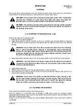
Page 72: ...mage to the engine and turbocharger 4 Shut down the engine by turning the ignition key to the OFF position Before leaving the cab remove the key and lock the cab 5 Turn off the electrical system master switch and remove the key before leaving the machine unattended 4 13 DRIVING THE MACHINE After starting the engine in temperature above 0 C do not start operations immediately First carry out the fo...

Page 73: ...ngine is warm completed warm up the equipment hydraulic system as follows a Move the boom control lever slowly to the RAISE position and raise the bucket slightly b Move the boom control lever slowly to the LOWER position and lower the bucket slightly c Repeat the above procedure several times gradually increasing stroke of the boom lift cylinders d Repeat steps a to c with the bucket control leve...

Page 74: ... to insure positive control movement e Before driving the machine adjust the seat and seat belt to fit snugly and low around the hips f Sound the horn to warn the nearby personnel g Never try to get on or off the machine when it is moving H Check all instruments gauges and warning lights for correct operation To start moving perform the following steps in accordance with Fig 4 22 1 Depress and hol...

Page 75: ...den braking of the machine For speed ranges in the respective gears refer to TRANSMISSION Section 6 ATTENTION Down shifting from 3 to 1 or 2 when driving at maximum speed may result in drive train damage UP SHIFTING An up shift from 1 to 2 or from 2 to 3 can be made at any speed To get proper acceleration speed up the machine to maximum speed before up shifting For speed ranges in the respective g...

Page 76: ...t the previously shifted gear the machine will brake suddenly what may result in loss of control or damage to the power train 3 Place transmission direction lever 45 in N neutral position and lock the lever in this position WARNING The transmission can remain in gear when the machine is brought to a temporary stop during operation However the operator must remain seated with the seat belt fastened...

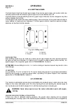
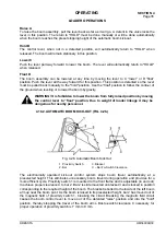
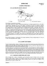
Page 77: ...vel checks 4 18 LOADER OPERATIONS Loader equipment is hydraulically operated When the bucket circuit is being operated oil flow to the boom is cut off 4 18 1 BOOM CONTROL LEVER POSITIONS FIGURE 4 25 Fig 4 25 Boom Control Lever Positions A Raise B Hold C Lower D Float IMPORTANT Holding the control lever in any position except B hold and D float for an extended period of time after the hydraulic cyl...

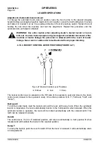
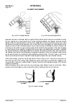
Page 78: ...e boom from fully raised position by moving the control lever to float position Due to weight of loader linkage it may be dangerous for nearby personnel 4 18 2 AUTOMATIC BOOM KICK OUT FIG 4 26 Fig 4 26 Automatic Boom Kick Out 1 Proximity Switch 2 Bar 3 Bracket C Bar To Switch Clearance The electronically operated kick out control system stops boom travel automatically at a preselected height This ...

Page 79: ...nder raised bucket without proper blocking 4 18 3 BUCKET CONTROL LEVER POSITIONS FIGURE 4 27 Fig 4 27 Bucket Control Lever Positions E Rollback B Hold C Dump The bucket control lever is situated on the RH side of the operator s seat and close to the boom control lever closest to the operator s seat It has three positions E B F roll back hold and dump Roll back E To roll the bucket back load the bu...

Page 80: ...osition and is resting on the ground Bar to switch clearance C necessary for the proper operation of the proximity switch is 7 mm to 8 mm No other adjustments are needed 4 19 LOADER TECHNIQUES Terrain footing conditions types of materials being worked and maneuvering space determine the speed at which the loader can function When the bucket is at work keep the engine speed at full throttle and ope...

Page 81: ... bucket edge immediately after penetration Operate the bucket control lever alternately between its roll back and dump positions This action will loosen the material and improve bucket loading Coordinated operation of the two hydraulic control levers as the bucket enters the material will yield satisfactory bucket loads The boom assy need not be fully raised to dump the bucket Adjust the dump heig...

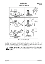
Page 82: ...position Keep the travel speed reasonable for safe operation Upon reaching the truck raise the bucket high enough to clear the truck body Fig 4 33 Dump load slowly to reduce the shock of weight transfer to the rear axle when the bucket is emptied Shake bucket only to loosen dirt from within WARNING Transport loads with bucket in carry position only A loaded bucket must never be transported in the ...

Page 83: ... and return to the loading site The bucket will automatically return to its pre set working position Lower loaded or unloaded bucket to the ground when waiting for any length of time WARNING Never travel with an unstable and solid rock 4 19 2 DIGGING CLEARING AND LEVELING When digging or excavating lower the bucket to the ground Adjust the angle of the cutting edge when the machines moves forward ...

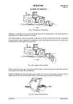
Page 84: ...tion the ground will be level Approach an excavation at the right angle and stop the front wheels at a safe distance from the edge of the excavation Fig 4 36 Clearing an Excavation When clearing a rocky area remove the small and loose rocks first large and solid rocks can then be loosened and moved with less difficulty Method of digging and removing large rocks is shown in Fig 4 37 It is easier to...

Page 85: ...he ground and scrapes and spreads uniformly The ground may be leveled as described above but with fixed boom position Selection of the method depends upon the local conditions and the operator Fig 4 38 Backdragging and Leveling Small or medium trees may be removed with bucket raised at operator s eyes level and positioned horizontally pushing the tree with the middle part of the bucket Do not hit ...

Page 86: ...d and push the tree from the site Fig 4 41 Removing Large Trees The wheel loader can be used for removing objects employing breakout force However avoid removing of spring materials because it may cause splitting of the material Employ breakout force available applying the load in the middle of the bucket width The wheel loader may be used for pushing and pressing against brick walls etc following...

Page 87: ...umption is quantity of moved material per unit of consumed fuel To reach the most favorable value of this ratio observe the following principles of loader operation avoid long distance transporting of material loading and pushing of material must be performed in a gear which ensures maximum drawbar pull at high torque converter efficiency take care to fill the bucket correctly during operation use...

Page 88: ...SECTION 5 MAINTENANCE ...

Page 89: ...18 5 6 4 Service Indicator Orifice Fitting 18 5 6 5 Precleaner Hood 19 5 7 Brakes 19 5 7 1 Service Brake System 19 5 7 2 Parking Brake 22 5 8 Cooling System 24 5 8 1 Water 24 5 8 2 Antifreeze 24 5 8 3 Inhibitors Conditioners 25 5 8 4 Radiator Cap 26 5 8 5 Checking the Coolant Level 26 5 8 6 Draining the System 27 5 8 7 Cleaning the System 27 5 8 8 Replacing the Coolant Filter 27 5 8 9 Filling the ...

Page 90: ...Hydraulic System Oil 44 5 14 3 Changing the Oil Filters 46 5 14 4 Servicing the Hydraulic Reservoir Breather 46 5 15 Seat Belt 47 5 16 Steering Gear 47 5 17 Tires and Rims 47 5 18 Transmission and Torque Converter 48 5 18 1 Checking the Oil Level 48 5 18 2 Changing the Oil 49 5 18 3 Changing the Oil Filters 49 5 18 4 Cleaning the Transmission Oil Strainer 50 5 18 5 Servicing the Breather 51 5 19 C...

Page 91: ...his machine may be serviced or to provide precaution for all the possible hazards that may result Safety is always the most important rule Constantly be aware of dangers involved in working on the machine and take proper precautions Standard and accepted safety precautions and equipment should be used This machine is assembled using high strength fasteners Do not substitute Replacement fasteners m...

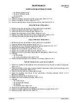
Page 92: ...es and clamps filter contamination Refer to 5 6 4 3 Lubricate the bucket link pins the bucket pivots Refer to 5 4 7 4 Clean transmission system suction strainer Refer to 5 18 4 5 Replace transmission system filters Refer to 5 18 3 6 Replace hydraulic system filters Refer to 5 14 3 after initial 50 hours of operation only Every 100 Hours of Operation 1 Perform the service as specified in Every 50 h...

Page 93: ...nsmission strainer Refer to 5 18 2 5 Replace the oil in hydraulic system Refer to 5 14 2 6 Replace the hydraulic tank filter elements Refer to 5 14 3 7 Replace the oil in the drive axles differential and planetaries Refer to 5 9 2 8 Lubricate the driveshafts the center articulation pivots refer to 5 4 7 9 Check and add electrolyte in the batteries if necessary Refer to 5 10 4 Periodic at least onc...

Page 94: ...N 1 Loader Equipment condition efficiency 2 Radiator condition evidence of leakage and condition of the grill 3 Hydraulic components condition leakage operation 4 Drive train condition leakage noise clearance 5 Wheels condition of tires mounting on wheel rims 6 Engine compartment fuel lubrication and the cooling system for leaks 7 Control panels check the condition and operation of instruments gau...

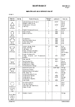
Page 95: ...reather Coolant for DCA 4 Filter Engine Crankcase Oil Torque Converter and Transmission Breather 10 1 2 1 1 1 1 MPG EO1 Lube Change Replace Clean Add change Change Clean Every 500 Hours 4 19 14 14 20 Drive Axle Oil Steering Gear Oil Transmission Filters Brake System Filters Tracking System linkage 2 1 2 1 4 MPL MPL MPG Check Check Replace Replace Lube Every 1000 Hours 1 1 1 4 11 13 13 13 18 Hydrau...

Page 96: ...ENACE AND SERVICE CHART DESCRIPTION E01 Engine Oil E02 Multigrade Engine Oil MPG Muli Purpose Grease HDTF Hydraulic Transmission Fluid MPL Multigrade Transmission Oil 5 3 1 SERVICE POINTS Fig 5 1 Service Points Service point description is given in Chart 1 ...

Page 97: ...rk being done load ground and weather conditions are all factors to consider in frequency of lubrication The scheduled intervals between the lubrication periods shown on the SERVICE CHART are approximate based on average operating conditions It may be necessary to lubricate after shorter working periods under severe operating conditions such as extreme dust low engine temperatures intermittent ope...

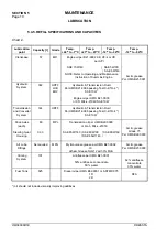
Page 98: ...il per HMS B21 0003 or CD MIL L 2104C SAE 10W Transmission and Converter System 144 HDTF Hydraulic Transmission Fluid Per HMS B21 0006 passing Test C 4 TO 4 SAE 10W Drive Axles each Steering Gear Housing 80 0 33 MPL Transmission oil per HMS B22 0003 or GL 5 MIL L 2105C SAE 85W 140 SAE 80W 90 SAE 80W 90 SAE 85W 140 Arctic grease Grade 75 Per HMS B22 0003 All Lube Fittings As required MPG Mylti purp...

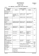
Page 99: ...D 30 Gear Lube per HMS B22 0003 or API GL 5 or MIL L 2105C MPL SAE 85W 140 HIPOL 85W 140 SPIRAX HD 85W 140 GEARTEX EP C 85W 140 SAE 80W 90 HIPOL 80W 90 SPIRAX HD 80W 90 GEARTEX EP C 80W 90 Multi purpose grease per HMS B27 0002 or NLGI grade 2 Multi purpose lithium grease with 3 minimum molybdenum disulfide MoS2 LITMOS EP 23 RETINAX EPX2 MOLYTEX EP 2 MPG Anti freeze ethylene glycol base per HMS B01...

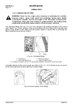
Page 100: ... greased at the intervals indicated in the service chart Always use a clean lubricator Wipe all accumulated dirt from fittings before applying fresh grease Apply grease at each fitting until fresh grease appears If grease fails to go through the fitting determine the cause and correct it Fig 5 2 Lubricating Fittings 1 Transfer Drive 2 Lower Articulation Pivot 3 Steering Cylinders 4 Upper Articulat...

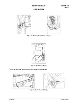
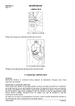
Page 101: ...E SECTION 5 Page 13 DRESSTA OM560C99 1E LUBRICATION Fig 5 4 Boom Cylinders Pivot Fittings Fig 5 5 Bellcrank Fittings Fittings are arranged symetrically on both sides of the bellcrank Fig 5 6 Boom Pivots Fittings ...

Page 102: ...outside for prolonged periods in sub zero weather will suffer from cold soak Lubricants become viscous and incapable of lubricating moving parts Extreme wear could result to the engine transmission and final drives unless proper precautions are taken A source of outside heat is necessary under these conditions There are electric as well as propane fired engine coolant heaters available Gas fired f...

Page 103: ... approved antifreeze based on ethylene glycol and coolant 8 Keep your cooling system clean and minimize corrosion by changing the coolant filter at correct intervals Refer to COOLING SYSTEM 5 5 3 ELECTRICAL SYSTEM Clean batteries and remove all corrosion from the battery terminals and cables Repair or replace all wires which have worn cracked or frayed insulation and broken or loose wires Service ...

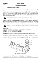
Page 104: ... remain in the element causing more frequent servicing of the element Use this method only as a temporary measure until sufficient time is available to clean the element by washing Always wash the filter element when contaminated with greasy dust WARNING After cleaning if an element is to be stored for later use place it in a plastic bag and store in an element shipping container to protect agains...

Page 105: ... low idle for 10 minutes before operating COMPRESSED AIR CLEANING 1 Carefully tap the side or end of the element against the palm of your hand to remove loose dust 2 Direct clean dry compressed air max pressure 200 kPa up and down the pleats on the inside of the element Always direct the flow of compressed air opposite the normal operating air flow direction through the element INSPECTION 1 Inspec...

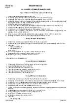
Page 106: ... body 3 Check the condition of the gasket at the end of the inner element 4 Clean the inside of body 10 with a damp cloth A small amount of non sudsing detergent added to the water will facilitate to remove the soot INSTALLATION 1 Install new inner element 9 the open end first into body 10 2 Install washer 5 wing nut 7 and secure with cotter key 8 3 Install outer element as described above 5 6 4 S...

Page 107: ...t and pull upward to remove the cap Use compressed air to clean the screen If compressed air is not available wash in clean hot water or water containing a small amount of nonsudsing detergent CAUTION Never wash precleaner installed on the machine as water may penetrate to the engine 5 7 BRAKES 5 7 1 SERVICE BRAKE SYSTEM A wheel loader is equipped with wet brakes inboard mounted close to the plane...

Page 108: ...ed The braking method is selected with the selector switch see INSTRUMENTS AND CONTROLS WARNING Do not use the braking method with the transmission disconnected when traveling fast or downhill Loss of control or damage to the power train could result when the pedal is released and the transmission re engages WARNING Aerated brake fluid lines reduce braking efficiency Take care to vent the lines pr...

Page 109: ...y the operator in the cab should depress lightly the brake pedal brake valve Let the oil with air flow until the outflowing oil is free from air bubbles 3 Turn off the vent valve and release the brake pedal 4 Install the protecting rubber cap 5 Check that the valves are securely tightened with the brake valve fully open Pour the drained clean oil into the transmission The venting procedure of the ...

Page 110: ...ND CONTROLS CHECKING THE OPERATION WARNING When testing the parking brake be sure the area near the machine is clear of personnel and obstructions because the machine may move during this test 1 Start and operate the engine at low idle to fill nitrogen accumulators and warm hydraulic system oil 2 Apply the parking brake if not applied 3 With the machine stopped with service brake and engine runnin...

Page 111: ...ake as follows PARKING BRAKE ADJUSTEMENT Adjustment of the parking brake is possible with the engine running and brake system operative only 1 Start and operate the engine at low idle to fill the nitrogen accumulators and warm the hydraulic system oil 2 Release the brake with the switch located on the instrument panel 3 With the parking brake released set the worm slack adjuster so as to obtain a ...

Page 112: ...which has a low mineral content Water used in conjunction with antifreeze coolant filters and inhibited water must meet the following standards Total hardness Not to exceed 170 parts per million to prevent scale deposits Water containing dissolved magnesium and calcium the usual reason for water hardness above the specified amount will cause scale deposits to develop in the engine Chlorides Not to...

Page 113: ...ain corrosion protection 2 SOLUBLE OIL IS NOT RECOMMMENDED for use in the engine as its use will reduce heat transfer Fig 5 16 Coolant Filter REPLENISHING COOLANT CONDITIONER Replenishing coolant conditioner is performed by periodical replacement of the filters Fig 5 16 containing DCA4 inhibitor protecting the cooling system against corrosion and cavitation erosion of the cylinder sleeves and cool...

Page 114: ...owly turning the cap to the first notch or lifting the safety lever if equipped Remove the cap only after the pressure is relieved To remove the cap press it down and turn until it is free to be removed Prior to removing the cap make sure all pressure is released When installing the cap the gasket and contacting surfaces must be clean Turn the cap to the right or clockwise until snug Fig 5 17 Radi...

Page 115: ...olant drain valves on the engine refer to Engine Operation and Maintenance Manual 4 Allow the system to drain completely 5 Remove the drain hose and install the castellated nut on the drain stub and shut the drain valves on the engine 6 Turn fully to the right the heater temperature control knob 32 in the cab to drain the coolant from the heater Refer to INSTUMENTS AND CONTROLS Fig 5 19 Radiator D...

Page 116: ...EPLACEMENT WARNING Hot scalding coolant can spray out if the radiator cap is removed suddenly Relieve system pressure by slowly turning the cap to the first notch or lifting the safety lever if equipped Remove the cap only after the pressure is relieved Fig 5 21 Shut Off Valve of Coolant Filter 1 Open the engine side access door on the left side of the machine 2 Open the radiator cap Close shut of...

Page 117: ...age may result to the filter seal or threads 8 After filter replacement turn shut off valve 1 Fig 5 21 to the open position located on the left side of the engine and reinstall the radiator cap 9 Start the engine and idle it for a few minutes Check the filter for possible coolant leakage 5 8 9 FILLING THE SYSTEM NOTE Be sure to fill the heater and heater supply lines with fresh coolant even if the...

Page 118: ...roud in the engine compartment on the right side of the engine compartment if equipped n the fuel cooler of QSK 19C engine located directly under the fan for QSK 19C engine only Access to the radiator is gained after removing bolts 1 Fig 5 25 and lifting the grill mounted on gas springs Fig 5 25 Cleaning Radiator Grill 1 Bolt 5 9 DRIVE AXLES WARNING Prior to servicing the machine block securely th...

Page 119: ...y enough to locate each planetary plug in turn to the lowest point for draining With the drain plugs in this position remove planetary plugs and drain oil Allow lubricant to drain thoroughly The above described steps should be performed for all four wheels Fig 5 27 Axle Filler Plug 3 Install the drain plugs in both axles In the first axle install the planetary plug only in one wheel Moving the mac...

Page 120: ...breakers Electrical system is protected with circuit breakers 10 amp 2 units 20 amp 1 unit 25 amp 1 unit and 30 amp 1 unit In the event of a short circuit or ground the circuit breaker will open before damage occurs and will continue to open and close until the trouble clears or is corrected When replacing use circuit breakers of the same amps To replace circuit breaker carry out as follows 1 Remo...

Page 121: ...voir When equipped with 2 maintenance free batteries or 8 batteries for arctic version they will be located in compartments on each side of the hydraulic reservoir When standard batteries are used the right hand compartment may be used as a tool storage compartment WARNING Batteries give off a highly flammable gas Do not smoke or allow sparks open flame near the batteries because a fire or explosi...

Page 122: ...attery to the machine frame Be sure the negative cable is 300 mm or more away from the battery The parking brake should be applied and transmission lever locked in neutral position ELECTROLYTE LEVEL The electrolyte in each cell must be at the proper level 21 to 27 mm above the plates at all times to prevent battery failure Check the level of the electrolyte When the electrolyte is below this level...

Page 123: ...il level is below L mark too low or above H too high at the dipstick see Fig 5 30 Check the oil level prior to starting the engine or at least 5 minutes after stopping the engine This allows the oil to drain back into the crankcase IMPORTANT Park the loader on level ground for correct oil level reading Fig 5 29 Location of Dipstick Fig 5 30 Engine Oil Dipstick 1 Filler Port 2 Dipstick 5 11 2 DRAIN...

Page 124: ...e filter is not filled with engine oil there will be a lack of lubrication during the delay until the filters are pumped full of oil This lack of lubrication is harmful to the engine 7 Install the filter on the filter header until the filter seal contacts the seal surface of the filter header and then turn the filter an additional 1 2 to 3 4 turn by hand Fig 5 34 Do not overtighten the filter or d...

Page 125: ...mage to the engine 5 11 5 FAN WARNING Damaged fan blades may cause serious injury Never pull the fan blades nor lift them This may damage the fan and cause injury NOTE Turn the fan as recommended by the engine manufacturer Inspect the fan for cracked and bent blades and loosened rivets Check that the fan is securely mounted Tighten the bolts if necessary A damaged fan must be replaced Fig 5 35 Fan...

Page 126: ... as the tension values for various belt widths For QSK 19 C 5 groove belt these values are as follows a new belt tension 670 N retension 270 to 530 N For KT 19 C 15 groove belt those values are as follows a new belt tension 1670 N retension 670 to 1340 N A belt is considered used when operated at least 10 minutes Alternately belt tension may be checked by pressing the belt midway between pulleys a...

Page 127: ... puncture the fluid container or put it into a fire Dispose of empty containers properly 8 For your safety remove the ether container when welding grinding or using a torch on the machine NOTE Improper starting fluids can cause valve seizure and severe damage to the engine Consult distributor for the recommended starting fluid to be used IMPORTANT The ether starting valve inlet must be sealed agai...

Page 128: ...ring components are necessary for long service life Always clean the area around the fuel tank filler cap before refueling WARNING Do not smoke while filling the fuel tank or servicing the fuel system because a fire or explosion could result WARNING When filling the fuel tank place the fuel nozzle against the side of the neck to reduce the chance of static electricity sparks WARNING Never remove t...

Page 129: ...side access cover on the right side of the machine 2 Clean the area around the fuel filters 3 Using a filter wrench remove the fuel filters by turning them counterclockwise Discard the filters in a suitable manner if they are not needed for any reason 4 Clean the fitter gasket surfaces of the filter header for each filter Fig 5 40 Replace the filter O rings Fig 5 41 Cleaning Fuel Filter Header Fig...

Page 130: ...e not to damage valve thread 5 13 2 FUEL TANK FUEL STRAINER The fuel strainer is installed in filler pipe 1 Fig 5 45 Access is possible upon the removal of the filler cap and retainer The fuel strainer performs a coarse filtration of the fuel facilitating the operation of the fuel filters Keep the fuel strainer clean Use kerosene or diesel fuel for cleaning FUEL LEVEL SIGHT GAUGE Fig 5 45 Fuel Tan...

Page 131: ...ts from the hydraulic reservoir clean the top surface of the reservoir and the components to be dismantled with a commercial cleaning solvent WARNING Before servicing the machine be sure the engine is off the bucket is lowered the transmission shift lever is locked in neutral N the parking brake is applied the electrical system disconnect switch is off and the key is removed WARNING This machine h...

Page 132: ...STEM OIL 1 Operate the boom bucket and steering circuits until the hydraulic oil becomes warm 2 Park the machine on level ground lower the bucket flat on the ground 3 Stop the engine and apply the parking brake 4 Open access cover 1 Fig 5 49 5 Clean the top of the reservoir with kerosene or cleaning solvent 6 Remove the plug from the reservoir drain valve Fig 5 50 7 Fit a short threaded pipe P N 4...

Page 133: ...kerosene and dry with compressed air 15 Replace the reservoir filters refer to 5 14 3 Close the drain valve Remove the drain pipe and hose from the drain valve Install the plug into the drain valve 16 Fill the reservoir with clean fluid until the ball in sight gauge 2 Fig 5 48 reaches the top of the gauge refer to REFILL SPECIFICATIONS AND CAPACITIES CHART 17 Install and tighten the filler cap 18 ...

Page 134: ...8 Install reservoir covers 2 Fig 5 49 9 Fill the reservoir per REFILL SPECIFICATIONS AND CAPACITIES CHART 5 14 4 SERVICING THE HYDRAULIC RESERVOIR BREATHER WARNING This machine has a pressurized reservoir Loosen the filler cap slowly to relive the pressure before disassembly of any hydraulic component 1 Loosen the reservoir cap slowly to relive the pressure 2 Remove lock ring 2 and cover 4 Fig 5 5...

Page 135: ...dles of oil grease or gasoline because this damages the tires INFLATION WARNING Never inflate a flat tire without inspecting the tire rim and wheel for damage Be sure all components are properly assembled Unmounted tires being inflated or deflated should be placed in a tire safety cage Inflate the tire to 35 kPa and check that all components are properly seated Never stand directly in front of a t...

Page 136: ...tor where persons with special training and safety tools are available 5 18 TRANSMISSION AND TORQUE CONVERTER 5 18 1 CHECKING THE OIL LEVEL WARNING When it is necessary to make any checks or adjustments with the engine running use two people A trained operator must be at the controls to safeguard the mechanic making the checks or adjustments Be sure the transmission shift lever is locked in neutra...

Page 137: ...nts of the transmission and torque converter and brake cooling systems as described in 5 18 3 and 5 7 1 4 Drain the transmission and torque converter completely and reinstall the drain plugs 5 Clean the transmission strainer as described in 5 18 4 6 Fill the transmission with fresh oil as described in 5 18 1 7 Prior to starting the machine check for leaks the following connections drain plugs tran...

Page 138: ...e engine and check the filters for leakage correct all leaks 13 Check the oil level as described in 5 18 1 5 18 4 CLEANIING THE TRANSMISSION OIL STRAINER FIG 5 56 1 The transmission should have been drained as described under 5 18 2 Install drain plugs 2 Disconnect tube 1 Protect its end against contamination 3 Remove retainer 3 gasket 4 check valve 5 gasket 6 and strainer assembly 7 4 Thoroughly ...

Page 139: ...her vents the entire drive train i e torque converter and transmission Remove the breather disassembly and wash the breather in a commercial cleaning solvent available 5 19 CAB Fig 5 58 Cab Mounting 1 Cab 2 Front Frame 3 Bolts Check periodically torque of ROPS cab mounting bolts Refer to Section 6 SPECIAL TORQUES 5 20 LOADER EQUIPMENT BUCKET INSTALLATION AND REMOVAL Fig 5 59 Bucket Installation 1 ...

Page 140: ...ins 2 out 4 Move away with the machine or lift the boom 5 Protect disassembled O rings 3 and 1 5 mm shims 4 6 Reinstall the bucket in the reverse order IMPORTANT Allowable gap between bucket supports and boom arms is 1 5 mm If gaps are bigger fill symmetrically with shims WARNING When replacing the bucket take care Disassembled heavy compo nents of loader linkage system boom arms connector must be...

Page 141: ...SECTION 6 SPECIFICATIONS ...

Page 142: ...trical System 17 6 8 5 Transmission 17 6 8 6 Torque Converter 17 6 8 7 Drive Axles 17 6 8 8 Tires 18 6 8 9 Rims 18 6 8 10 Brakes 18 6 8 11 Loader Hydraulic System 18 6 8 12 Cycle Times 18 6 8 13 Fuel Consumption 18 6 9 560C Loader Equipment 19 6 10 Torque Values for Standard Metric Fasteners 20 6 11 Torque Values for Standard English Fasteners 21 6 12 Torque Values for Split Flange Connections 22 ...

Page 143: ......
Page 144: ...oscillates allowing the machine to operate in uneven ground The chassis comprises hydraulic compressed air electrical and cooling systems as well as drive train that consists of torque converter transmission drive shafts drive axles SUPERSTRUCTURE The superstructure consists of a front mounted cab hood fenders and platforms oil fuel and air tanks The instrument panel located in the cab includes ga...

Page 145: ...SECTION 6 SPECIFICATIONS Page 4 OM560C99 1E DRESSTA 6 3 SCHEMATIC OF WHEEL LOADER DRIVE TRAIN Fig 6 1 Wheel Loader Drive Train Schematic ...

Page 146: ... 5 Rear Drive Axle 6 9 Drive Shafts 10 Transfer Drive 11 Parking Brake 12 Bolster 13 Service Brake 14 Ground Driven Steering Pumps F R S1 S2 S3 Clutches 6 4 SCHEMATIC OF TORQUE CONVERTER AND TRANSMISSION HYDRAULIC SYSTEM Fig 6 2 Schematic of Torque Converter and Transmission Hydraulic System 1 Pump 2 Torque Converter 3 Transmission 4 Pressure Filter 5 Regulating Valves 6 Steering Valves 7 Radiator...

Page 147: ...SECTION 6 SPECIFICATIONS Page 6 OM560C99 1E DRESSTA 6 5 LOADER EQUIPMENT AND STEERING HYDRAULIC SYSTEM SCHEMATIC Fig 6 3 Loader Equipment and Steering Hydraulic System Schematic ...

Page 148: ...ulic Reservoir 2 Strainers 3 Bypass Valve 4 Hydraulic Pump 5 Return Filters 6 Measurement Point 7 Oil Cooler 8 Surge Valve 9 Hydraulic Control Valve 10 Double Gear Pump with Diverter Valve 11 Steering Valve 12 Pilot Control Valve 13 Ground Driven Steering System 14 Ground Driven Steering Pump 15 Warning Light Switch 16 Boom Cylinders 2 17 Bucket Cylinder 18 Steering Cylinders 2 19 Check Valve ...

Page 149: ...SECTION 6 SPECIFICATIONS Page 8 OM560C99 1E DRESSTA 6 6 BRAKE HYDRAULIC SYSTEM SCHEMATIC Fig 6 4 Brake Hydraulic System Schematic ...

Page 150: ...mulator 6 Brake Valve Brake Pedal 7 Parking Brake Solenoid Valve 8 Parking Brake Hydraulic Cylinder 9 Differential Valve 10 Cooling System Low Pressure Switch 11 Valve Block 12 Transmission Disconnect Solenoid Valve 13 Parking Brake Warning Light Switch 14 Suction Strainer 15 Wheel Brake Assembly 16 Wheel Brake Piston 17 Supply From Transmission System 18 Transmission Oil Reservoir 19 Supply of Tr...

Page 151: ...SECTION 6 SPECIFICATIONS Page 10 OM560C99 1E DRESSTA 6 7 WIRING DIAGRAM Fig 6 5 Wiring Diagram ...

Page 152: ...h 27 Battery 28 Air Conditioner Low Pressure Switch if equipped 29 Hydraulic Accumulators Gas Pressure Switches 30 Cooling Brake Low Pressure Switch 31 Directional Neutral Safety Switch 32 Brake System Differential Pressure Switch 33 Brake System Oil Filter Warning Light Switch 34 Ground Drive Steering Alarm and Lamp Switch 35 Main Brake Low Pressure Switches 36 Back up Alarm 37 Parking Brake Warn...

Page 153: ...ional Lamp If Equipped 69 Front Left Work Lamp 70 Horn 71 Low Level Work Lamp If Equipped 72 Front Right Directional Lamp If Equipped 73 Front Right Work Lamp 74 Horn 75 Boom Raise Limit Magnetic Switch 76 Boom Raise Limit Electromagnet 77 Boom Rise Limit Magnetic Switch Relay 78 Bucket Dump Limit Magnetic Switch 79 Bucket Dump Limit Electromagnet 80 Bucket Dump Limit Magnetic Switch Relay 81 Engi...

Page 154: ...SPECIFICATIONS SECTION 6 Page 13 DRESSTA OM560C99 1E WIRING DIAGRAM Fig 6 6 Wiring Diagram Of Cab ...

Page 155: ...tor 7 Front Window Washer Pump Button 8 Rear Window Washer Pump Button 9 Rear Wipers Motor Switch 10 Front Wiper Motor Switch 11 Defroster Fan Motor Switch 12 Heater Fan Motor 13 Heater Fan Motor Switch 14 Resistor 15 Heater Switch 16 Thermostat 17 Supply Connector 18 Top Work Lamp 19 Front Wiper Motor Wire color code R red O orange T brown P pink W white V violet Y yellow DB dark blue B black LB ...

Page 156: ...ight 282 kN full turn 250 6 kN Operating weight 41800 kg Load capacity kN 10 125 3 Overall length with bucket L7 9520 mm Turning radius outside corner of bucket carry 8600 mm Articulation 35 Tread W3 2590 mm Wheelbase L3 3940 mm Height to the top of cab H1 4110 mm Ground clearance H4 500 mm Machine width W1 3380 mm Axle oscillation 11 5 Operating weight LOGGER version Grapple 90 108 119 50011 kg G...

Page 157: ...tines level 2730 mm 2940 mm F Reach at maximum dump and maximum lift 2000 mm 2170 mm G Maximum tine height with tines level 4540 mm 4540 mm J Maximum overall height 9390 mm 9390 mm L Maximum grapple rollback at ground 9 5 9 5 Grapple width not shown in Fig 6 3500 mm 3500 mm 6 8 2 CAPACITIES Refill Service Fuel tank 625 l Cooling system 101 l Front axle 80 l Rear axle 80 l Hydraulic system loader a...

Page 158: ...t torque 1831 Nm at rpm 1300 rpm 1500 rpm Engine speeds High idle 2200 2350 rpm Governed speed 2100 rpm Full load 1475 1730 rpm Low idle 675 775 rpm 6 8 4 ELECTRICAL SYSTEM Voltage 24 V Batteries 2 x 12 V Negative ground Alternator 80 A 6 8 5 TRANSMISSION Model P 3000 Type powershift Maximum travel speeds forward reverse km h 1st gear 7 1 7 1 2nd gear 12 2 12 2 3rd gear 32 5 32 5 6 8 6 TORQUE CONV...

Page 159: ...spring applied Hydraulically released 6 8 11 LOADER HYDRAULIC SYSTEM Main control valve Standard 2 spool Optional 3 spool Pilot control valve Standard 2 spool Optional 3 spool 6 8 12 CYCLE TIMES Boom raise 9 1 s Boom lower 9 3 s Bucket dump 2 8 s 35 articulation 1 5 s 6 8 13 FUEL CONSUMPTION During tests consisting in intensive operation of a loader in excavation sandy soil bulk density 1 6 t cu m...

Page 160: ...cket w o teeth Fig 6 9 Spade Nose Buckets Bucket capacity 5 35 cu m 5 73 cu m and 5 73 cu m Applications quarry A bucket w teeth B bucket w o teeth Fig 6 10 Straight Edge Buckets Bucket capacity 5 35 cu m 6 5 cu m 11 5 cu m Applications reloading operations 6 5 cu m light materials coal coke 11 5 cu m ...

Page 161: ...rd hardware Original equipment standard hardware is defined as coarse thread metric class 10 9 bolts and class 10 0 nuts and thru hardened flat washers Rockwell C 38 45 all phosphate coated and assembled without supplemental lubrication as received condition The torques shown below apply to phosphate coated bolts designed for 60 yield strength The torques shown below also apply to phosphate coated...

Page 162: ...log for the machine involved DO NOT SUBSTITUTE Original equipment standard hardware is defined as Type 8 coarse thread bolts and nuts and thru hardened flat washers Rockwell C 38 45 all phosphate coated and assembled without supplemental lubrication as received condition Phosphate coated bolts used in tapped holes in steel or gray iron phosphate coated bolts used with phosphate coated prevailing t...

Page 163: ...following chart 3 provides the tightening torques for split flange connections used in hydraulic systems Split flanges and fitting shoulders should fit squarely Install all bolts finger tighten and then torque evenly Overtorquing bolts will damage the flanges and or bolts which may cause leakage Chart 3 Bolt size in inches Flange size in inches Torque Value Nm 1 2 5 16 20 24 3 4 3 8 30 37 1 3 8 37...

Page 164: ...156 24 1 1 2 2 1 2 12 217 237 163 190 32 2 2 1 2 12 305 325 339 407 Above torque figures are recommended for plain cadmium or zinc plated fittings dry or wet installations These torques are not recommended for tube with wall thickness of 0 89 mm or less 6 14 TORQUE VALUES FOR HOSE CLAMPS The following chart 5 provides the tightening torques for hose clamps used in all rubber applications radiator ...

Page 165: ...l 1 4 7 16 20 16 23 15 20 15 20 12 18 3 8 5 8 18 27 33 23 38 23 38 20 25 1 2 3 4 16 47 54 38 46 38 46 28 36 5 8 7 8 14 61 68 45 53 45 53 34 32 3 4 1 1 6 12 72 80 49 57 49 57 45 53 1 1 6 14 72 80 49 57 49 57 45 53 6 16 TORQUE VALUES FOR AIR CONDITIONING 0 RING CONNECTIONS Chart 8 Thread Torque values for materials Nm Size size in inches Steel steel 1 4 7 16 20 15 25 3 8 5 8 18 27 33 1 2 3 4 16 40 4...

Page 166: ... 1300 Radiator grill fastening bolts 5 8 220 Counterweight fastening bolts 1 1800 Oil tank frame mounting bolts 390 Fuel tank mounting bolts 390 Ladder mounting bolts 110 Steering mechanism mounting bolts arm mounting to the frame tracking system support trunnion steering wheel nut 5 8 1 170 220 110 300 48 Pin mounting bolts boom frame boom bucket hydraulic cylinders boom boom cylinder frame boom ...

Page 167: ...r Filter covers on equipment and steering hydraulic tank Nuts fastening filter elements in hydraulic tank Transmission strainer cover 1 1 8 Coolant drain plug not applicable for machines sold in EC market Engine oil drain plug not applicable for machines sold in EC market Fuel tank breather Transmission breather 1 Axle filler plug Axle drain plug Transmission drain plug 1 Brake system deaeration t...

Reviews:

Related manuals for 560C