SECTION 5
MAINTENANCE
Page 18
OM560C99/1E
DRESSTA
AIR CLEANING SYSTEM
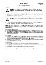
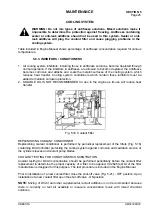
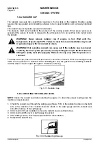
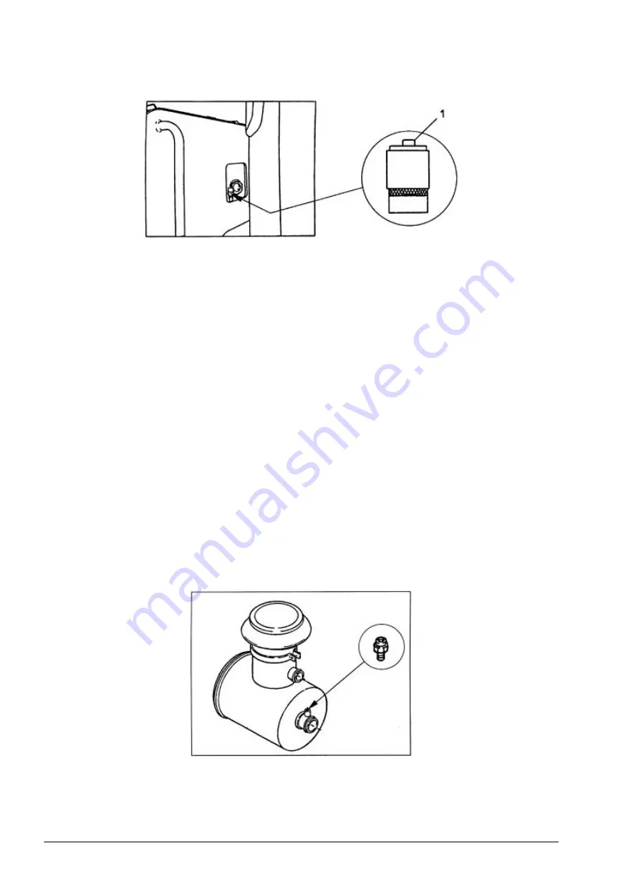
Fig. 5.10. Air Cleaner Service Indicator
1. Reset button
4. Start the engine. If the air cleaner service indicator light indicates air restriction, stop the engine
and replace outer or outer and inner filter elements.
5.6.3. INNER FILTER ELEMENT
Replace the inner element with every third change of the outer element or when plugged, as shown
by the service indicator.
REMOVAL
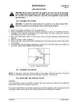
1. Remove the outer element as described above.
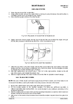
2. Remove cotter key 8, nut 7 and washer 5 and pull inner element 9 out of the body.
3. Check the condition of the gasket at the end of the inner element.
4. Clean the inside of body 10 with a damp cloth. A small amount of non-sudsing detergent added
to the water will facilitate to remove the soot.
INSTALLATION
1. Install new inner element 9 the open end first into body 10.
2. Install washer 5, wing nut 7 and secure with cotter key 8.
3. Install outer element as described above.
5.6.4. SERVICE INDICATOR ORIFICE FITTING
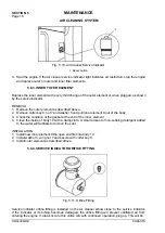
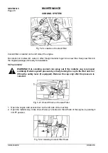
Fig. 5.11. Orifice Fitting
Service indicator orifice fitting is installed on the air cleaner elbow close to the service indicator.
If the indicator or its tubing becomes damaged, the orifice fitting will prevent unfiltered air from
entering the engine. If a leak occurs, this orifice will, with continued operation, plug up. This will be
Summary of Contents for 560C
Page 1: ...OM560C99 1E OPERATOR S MANUAL 560C SERIAL NUMBERS 15001 AND UP ...
Page 3: ......
Page 5: ......
Page 7: ......
Page 10: ...SECTION 1 INTRODUCTION ...
Page 12: ......
Page 16: ...SECTION 2 SAFETY PRECAUTIONS ...
Page 18: ......
Page 32: ...SECTION 3 MACHINE TRANSPORT AND STORAGE ...
Page 34: ......
Page 42: ...SECTION 4 OPERATING ...
Page 43: ......
Page 45: ......
Page 49: ...SECTION 4 OPERATING Page 6 OM560C99 1E DRESSTA UNIVERSAL SYMBOLS FOR INSTRUMENTS AND CONTROLS ...
Page 88: ...SECTION 5 MAINTENANCE ...
Page 141: ...SECTION 6 SPECIFICATIONS ...
Page 143: ......

