SECTION 5
MAINTENANCE
Page 26
OM560C99/1E
DRESSTA
COOLING SYSTEM
5.8.4. RADIATOR CAP
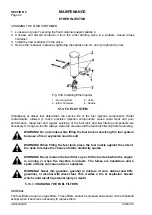
The radiator cap seals the coolant filler opening in the top tank of the radiator. Positive sealing
requires the cap gasket and contacting surfaces to be in good condition and a properly tightened
cap.
The radiator cap incorporates a pressure relief valve.
The pressure relief valve maintains the pressure of the cooling system. When preset pressure is
exceeded the excess of steam is released to the atmosphere thru an overflow tube routed under
the radiator.
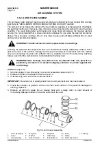
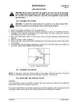
WARNING! Never remove radiator cap if engine is hot. Wait until the
temperature drops below 50
°°
C. Failure to meet this recommendation may result
in personal injury with hot coolant or steam.
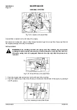
WARNING! Hot, scalding coolant can spray out if the radiator cap is removed
suddenly. Relieve system pressure by slowly turning the cap to the first notch or
lifting the safety lever (if equipped). Remove the cap only after the pressure is
relieved.
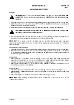
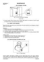
To remove the cap, press it down and turn until it is free to be removed. Prior to removing the cap
make sure all pressure is released. When installing the cap, the gasket and contacting surfaces
must be clean. Turn the cap to the right or clockwise until snug.
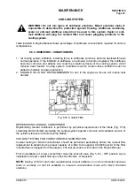
Fig. 5.17. Radiator Cap
5.8.5. CHECKING THE COOLANT LEVEL
NOTE
:
Check the coolant level before starting the engine. To obtain the proper reading place the
machine on level ground.
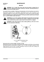
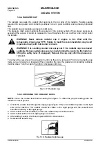
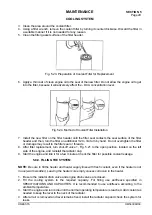
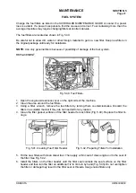
1. Check the coolant level through the sight gauge (Figure 5.18) in the radiator top tank on the right
side of the machine. The coolant should be visible in the sight gauge and the coolant level
should be midway of the sight gauge.
2. Add coolant if it must be added; remove the radiator cap as outlined above.
3. Add coolant until the level in sight gauge in reached.
4. After adding coolant, check and replenish DCA4 concentration.
5. Reinstall the radiator cap.
Fig. 5.18. Radiator Sight Gauge
Summary of Contents for 560C
Page 1: ...OM560C99 1E OPERATOR S MANUAL 560C SERIAL NUMBERS 15001 AND UP ...
Page 3: ......
Page 5: ......
Page 7: ......
Page 10: ...SECTION 1 INTRODUCTION ...
Page 12: ......
Page 16: ...SECTION 2 SAFETY PRECAUTIONS ...
Page 18: ......
Page 32: ...SECTION 3 MACHINE TRANSPORT AND STORAGE ...
Page 34: ......
Page 42: ...SECTION 4 OPERATING ...
Page 43: ......
Page 45: ......
Page 49: ...SECTION 4 OPERATING Page 6 OM560C99 1E DRESSTA UNIVERSAL SYMBOLS FOR INSTRUMENTS AND CONTROLS ...
Page 88: ...SECTION 5 MAINTENANCE ...
Page 141: ...SECTION 6 SPECIFICATIONS ...
Page 143: ......

