MAINTENANCE
SECTION 5
Page 29
DRESSTA
OM560C99/1E
COOLING SYSTEM
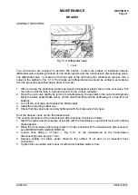
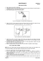
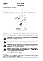
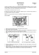
3. Clean the area around the coolant filter.
4. Using a filter wrench, remove the coolant filter by turning it counterclockwise. Discard the filter in
a suitable manner if it is not needed for any reason.
5. Clean the filter gasket surface of the filter header.
Fig. 5.23. Preparation of Coolant Filter for Replacement
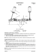
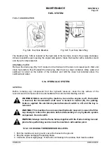
6. Apply a thin coat of clean engine oil to the seal of the new filter. Do not allow the engine oil to get
into the filter, because it will adversely affect the - DCA concentration level.
Fig. 5.24. Method of Coolant Filter Installation
7. Install the new filter on the filter header until the filter seal contacts the seal surface of the filter
header and then, turn the filter an additional 1/2 to 3/4 turn by hand. Do not overtighten the filter
or damage may result to the filter seal or threads.
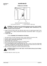
8. After filter replacement, turn shut-off valve 1, Fig. 5.21 to the open position, located on the left
side of the engine, and reinstall the radiator cap.
9. Start the engine and idle it for a few minutes. Check the filter for possible coolant leakage.
5.8.9. FILLING THE SYSTEM
NOTE:
Be sure to fill the heater and heater supply lines with fresh coolant, even if the heater is not
in use (warm weather). Leaving the heater core empty causes corrosion in the heater.
1. Be sure the radiator drain valve and engine drain valves are closed.
2. Fill the cooling system to the required capacity. For filling use antifreeze specified in
SPECIFICATIONS AND CAPACITIES. It is recommended to use antifreeze according to the
ambient temperature.
3. Start the engine and run it idle until the normal operating temperature is reached. Add coolant as
needed to keep the level to the neck of the radiator.
4. After all air is removed and level remains fixed, install the radiator cap and check the system for
leaks.
Summary of Contents for 560C
Page 1: ...OM560C99 1E OPERATOR S MANUAL 560C SERIAL NUMBERS 15001 AND UP ...
Page 3: ......
Page 5: ......
Page 7: ......
Page 10: ...SECTION 1 INTRODUCTION ...
Page 12: ......
Page 16: ...SECTION 2 SAFETY PRECAUTIONS ...
Page 18: ......
Page 32: ...SECTION 3 MACHINE TRANSPORT AND STORAGE ...
Page 34: ......
Page 42: ...SECTION 4 OPERATING ...
Page 43: ......
Page 45: ......
Page 49: ...SECTION 4 OPERATING Page 6 OM560C99 1E DRESSTA UNIVERSAL SYMBOLS FOR INSTRUMENTS AND CONTROLS ...
Page 88: ...SECTION 5 MAINTENANCE ...
Page 141: ...SECTION 6 SPECIFICATIONS ...
Page 143: ......

