MAINTENANCE
SECTION 5
Page 39
DRESSTA
OM560C99/1E
ENGINE
ADJUSTMENT
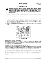
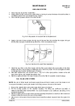
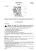
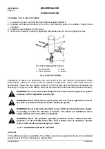
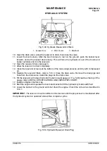
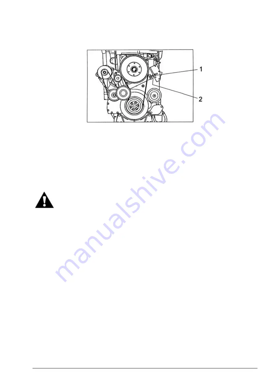
Fig. 5.38. Fan Belt Adjustment
Loosen nut 2 to the end of the thread. Tension by hand the adjuster roller until it contacts with the
belt. Tighten nut 1 finger tight, then tighten nut 1 using a wrench by 9 turns. Torque nut 2 to 81 Nm.
5.12. ETHER INJECTOR
PRECAUTIONS
WARNING! Ether starting fluid is highly flammable. Follow strictly the
precautions on the container. An explosion can result if sparks or flame contact
the ether or if the container is stored where the temperature exceeds 70°C.
1. Do not use the ether injector when the air temperature is above freezing (0°C).
2. Do not smoke when using ether starting fluid.
3. Do not store fluid containers in the operator's compartment.
4. Keep the fluid containers out of reach of children.
5. Do not breathe the hazardous ether vapor.
6. Do not let ether contact you skin, because it can cause frostbite.
7. Never puncture the fluid container or put it into a fire. Dispose of empty containers properly.
8. For your safety, remove the ether container when welding, grinding, or using a torch on the
machine.
NOTE:
Improper starting fluids can cause valve seizure and severe damage to the engine. Consult
distributor for the recommended starting fluid to be used.
IMPORTANT:
The ether starting valve inlet must be sealed against the entry of dirt at all times by
having a container installed or by installing the dust cap provided with the valve.
INSPECTION AND CLEANING
Make certain that ether is available under pressure. To do so, remove the ether container and check
if a good spray is obtained. If not, replace with a new container. If a good spray was obtained, install
the container and test the ether injector as follows:
1. Disconnect the ether tube at the spray nozzle in the engine manifold. Remove the spray nozzle.
2. Reconnect the nozzle to the tube.
3. Direct the nozzle away from the engine and actuate the ether injector.
4. Dribbling or no spray indicates a blocked spray nozzle or tube. If necessary, clean or replace
nozzle and/or tube.
Summary of Contents for 560C
Page 1: ...OM560C99 1E OPERATOR S MANUAL 560C SERIAL NUMBERS 15001 AND UP ...
Page 3: ......
Page 5: ......
Page 7: ......
Page 10: ...SECTION 1 INTRODUCTION ...
Page 12: ......
Page 16: ...SECTION 2 SAFETY PRECAUTIONS ...
Page 18: ......
Page 32: ...SECTION 3 MACHINE TRANSPORT AND STORAGE ...
Page 34: ......
Page 42: ...SECTION 4 OPERATING ...
Page 43: ......
Page 45: ......
Page 49: ...SECTION 4 OPERATING Page 6 OM560C99 1E DRESSTA UNIVERSAL SYMBOLS FOR INSTRUMENTS AND CONTROLS ...
Page 88: ...SECTION 5 MAINTENANCE ...
Page 141: ...SECTION 6 SPECIFICATIONS ...
Page 143: ......

