SECTION 5
MAINTENANCE
Page 46
OM560C99/1E
DRESSTA
HYDRAULIC SYSTEM
5.14.3. CHANGING THE OIL FILTERS
Replace the oil filters when changing oil or earlier, when filter warning light comes on.
1. Drain the reservoir as described in 5.14.2.
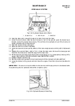
2. Remove reservoir covers 2, Fig. 5.49.
3. Remove the two filter elements 2 from inside of the reservoir.
4. Clean the reservoir screens at the bottom of the tank using kerosene and dry with compressed
air.
5. Install new filter elements. Torque mounting nuts to 14-16 Nm
6. Install the plug into the drain valve.
7. Close the drain valve.
8. Install reservoir covers 2, Fig. 5.49.
9. Fill the reservoir per REFILL SPECIFICATIONS AND CAPACITIES CHART.
5.14.4. SERVICING THE HYDRAULIC RESERVOIR BREATHER
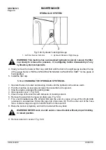
WARNING! This machine has a pressurized reservoir. Loosen the filler cap
slowly to relive the pressure before disassembly of any hydraulic component.
1. Loosen the reservoir cap slowly to relive the pressure.
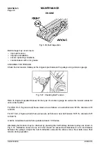
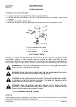
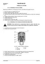
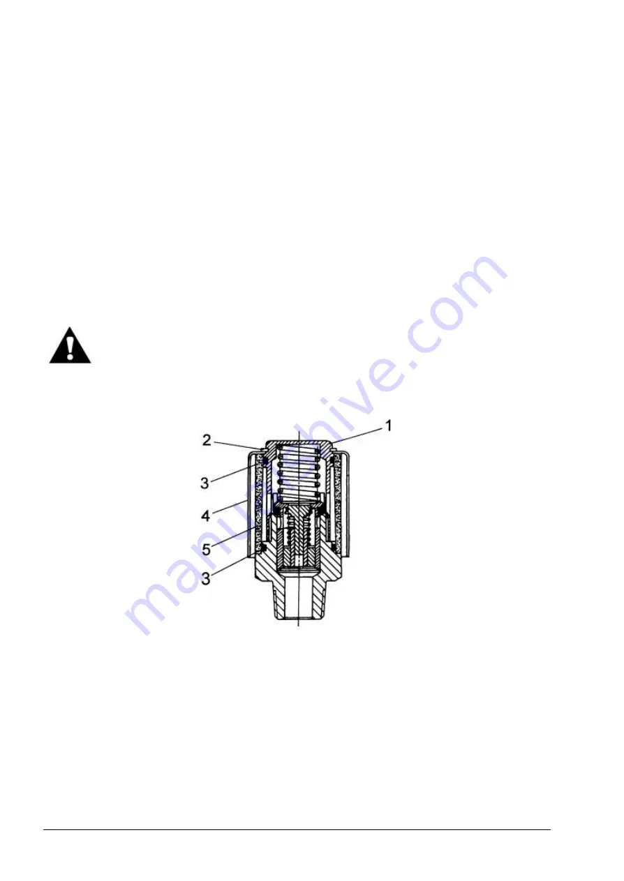
2. Remove lock ring 2 and cover 4.
Fig. 5.51. Hydraulic Reservoir Breather
1 - Cap
2 - Lock Ring
3 - Seal Ring
4 - Cover
5 - Filter
3. Remove filter 5 and clean in a commercial solvent and dry with compressed air.
4. Check seal rings 3 for wear or deterioration. Replace if necessary.
5. Reinstall filter 5 and cover 4. Secure with ring 2.
6. Tighten the reservoir filler cap.
7. Service the other breather in a similar manner.
Summary of Contents for 560C
Page 1: ...OM560C99 1E OPERATOR S MANUAL 560C SERIAL NUMBERS 15001 AND UP ...
Page 3: ......
Page 5: ......
Page 7: ......
Page 10: ...SECTION 1 INTRODUCTION ...
Page 12: ......
Page 16: ...SECTION 2 SAFETY PRECAUTIONS ...
Page 18: ......
Page 32: ...SECTION 3 MACHINE TRANSPORT AND STORAGE ...
Page 34: ......
Page 42: ...SECTION 4 OPERATING ...
Page 43: ......
Page 45: ......
Page 49: ...SECTION 4 OPERATING Page 6 OM560C99 1E DRESSTA UNIVERSAL SYMBOLS FOR INSTRUMENTS AND CONTROLS ...
Page 88: ...SECTION 5 MAINTENANCE ...
Page 141: ...SECTION 6 SPECIFICATIONS ...
Page 143: ......

