SPECIFICATIONS
SECTION 6
Page 25
DRESSTA
OM560C99/1E
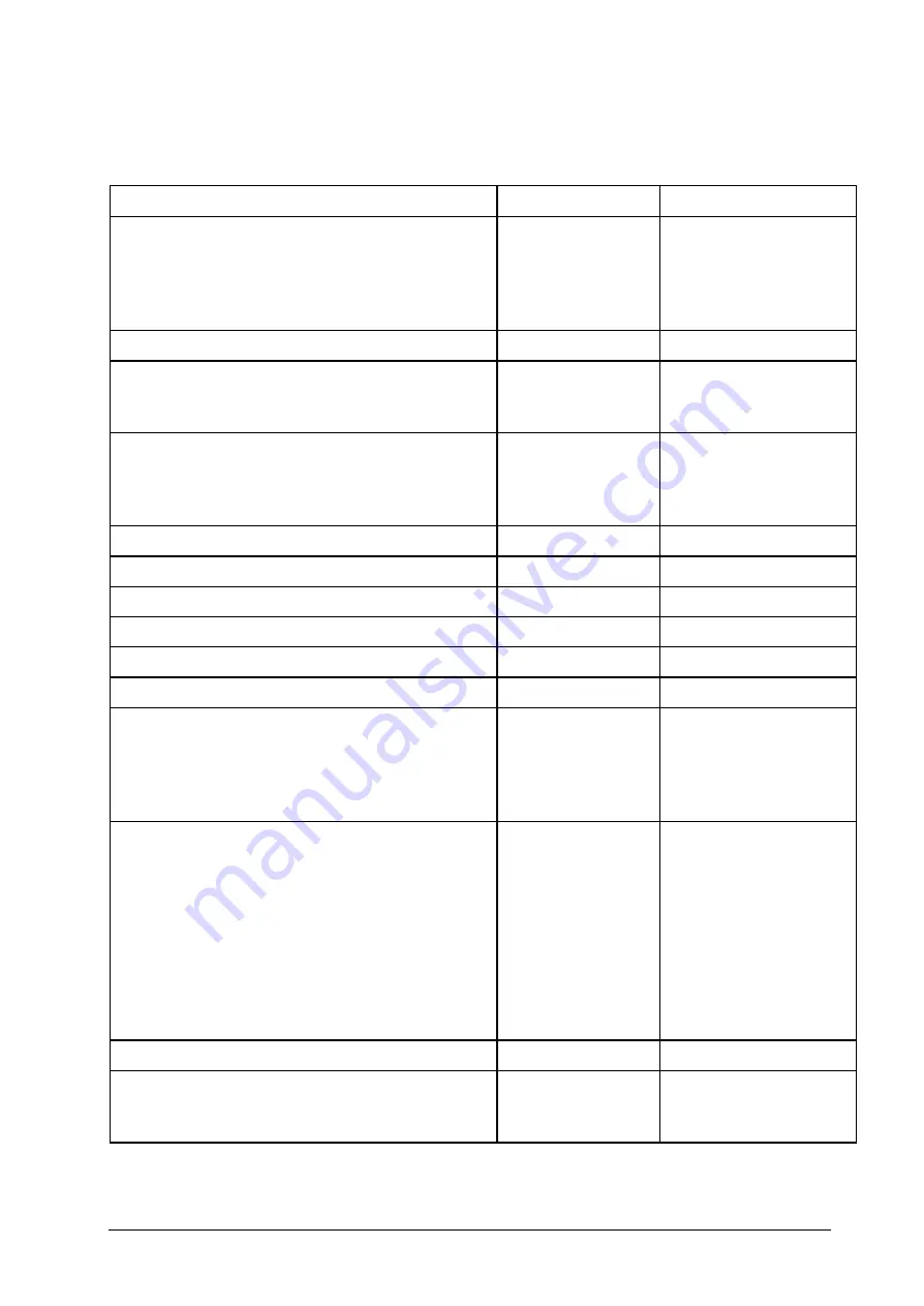
6.17. SPECIAL TORQUES
Chart 9
Description
Thread Size
Torque Nm
U-joint fastening bolts:
•
Transmission-planetary
•
Transmission- rear axle
•
Transmission- support
•
Support- front axle
½
½
½
½
130
130
130
130
Drive axle fastening bolts:
1-1/2
3180
Transmission fastening bolts:
•
Support to transmission
•
Support to frame
¾
1
390
390
Engine mounting bolts:
•
Engine - frame (at fan)
•
Support frame (at flywheel)
•
Gear ring - flywheel
1
5/8
1/2
940
220
83
Wheel lug nuts
1
1250-1300
Radiator grill fastening bolts
5/8
220
Counterweight fastening bolts
1-¼
1800
Oil tank frame mounting bolts
¾
390
Fuel tank mounting bolts
¾
390
Ladder mounting bolts
½
110
Steering mechanism mounting bolts:
•
arm
•
mounting to the frame
•
tracking system support trunnion
•
steering wheel nut
5/8
1
-
170-220
110
300
48
Pin mounting bolts:
•
boom - frame
•
boom - bucket
•
hydraulic cylinders - boom
•
boom cylinder - frame
•
boom cylinder - bellcrank
•
bellcrank - link
•
link - bucket
•
steering cylinders - frame
•
bolster - frame
1-1/8
1-1/8
1-1/8
1-1/8
1-1/8
1-1/8
1-1/8
¾
¾
820
820
820
820
820
820
820
280
280
Transfer drive line mounting bolts
3/4
390
Cab mounting bolts:
•
cab - floor
•
floor - frame
3/8
1
47
940
Tightening torque tolerance
±
10%.
Summary of Contents for 560C
Page 1: ...OM560C99 1E OPERATOR S MANUAL 560C SERIAL NUMBERS 15001 AND UP ...
Page 3: ......
Page 5: ......
Page 7: ......
Page 10: ...SECTION 1 INTRODUCTION ...
Page 12: ......
Page 16: ...SECTION 2 SAFETY PRECAUTIONS ...
Page 18: ......
Page 32: ...SECTION 3 MACHINE TRANSPORT AND STORAGE ...
Page 34: ......
Page 42: ...SECTION 4 OPERATING ...
Page 43: ......
Page 45: ......
Page 49: ...SECTION 4 OPERATING Page 6 OM560C99 1E DRESSTA UNIVERSAL SYMBOLS FOR INSTRUMENTS AND CONTROLS ...
Page 88: ...SECTION 5 MAINTENANCE ...
Page 141: ...SECTION 6 SPECIFICATIONS ...
Page 143: ......

