SECTION 4
OPERATING
Page 24
OM560C99/1E
DRESSTA
4.7. AIR CLEANER SERVICE INDICATOR
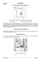
Fig. 4.15. Service Indicator and Hydraulic Reservoir Sight Gauge
1. Service Indicator
2. Hydraulic Reservoir Sight Gauge
During operation, the red band will gradually rise in the indicator window as dirt accumulates in the
air filter elements. When the filter elements reach the maximum allowable restriction, the red band
will completely fill the indicator window and automatically lock in this position. The red band will
remain fully exposed even after stopping the engine. Press the reset button on top of indicator after
the elements have been serviced.
4.8. DOME LIGHTS WITH SWITCHES
Dome lights are installed in the roof of the cab on the right and left hand side of operator’s head.
The lights are equipped with switches.
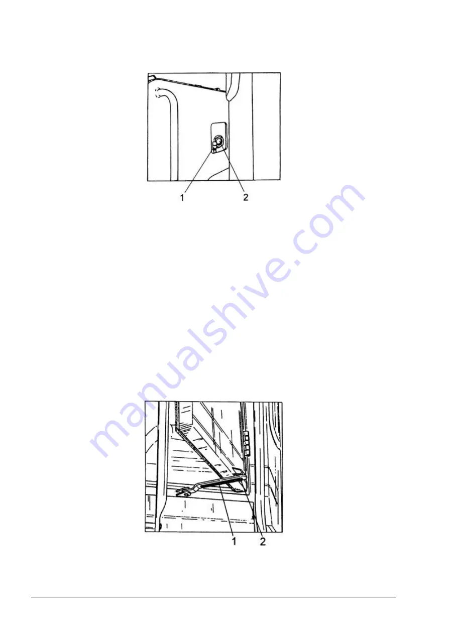
4.9 CAB DOOR LATCH
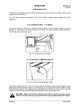
The cab door may be locked in an open position. The latch is particularly useful for cab ventilation
when operating in high ambient temperatures.
Fig. 4.16. Cab Door Latch
1 - Arm
2 - Pin
Summary of Contents for 560C
Page 1: ...OM560C99 1E OPERATOR S MANUAL 560C SERIAL NUMBERS 15001 AND UP ...
Page 3: ......
Page 5: ......
Page 7: ......
Page 10: ...SECTION 1 INTRODUCTION ...
Page 12: ......
Page 16: ...SECTION 2 SAFETY PRECAUTIONS ...
Page 18: ......
Page 32: ...SECTION 3 MACHINE TRANSPORT AND STORAGE ...
Page 34: ......
Page 42: ...SECTION 4 OPERATING ...
Page 43: ......
Page 45: ......
Page 49: ...SECTION 4 OPERATING Page 6 OM560C99 1E DRESSTA UNIVERSAL SYMBOLS FOR INSTRUMENTS AND CONTROLS ...
Page 88: ...SECTION 5 MAINTENANCE ...
Page 141: ...SECTION 6 SPECIFICATIONS ...
Page 143: ......

