SECTION 4
OPERATING
Page 26
OM560C99/1E
DRESSTA
4.12. STARTING AND STOPPING THE ENGINE
4.12.1. NORMAL START (AMBIENT TEMPERATURE ABOVE 0
°°
C)
WARNING: DO NOT jump on or off the machine. Keep two hands and one foot,
or two feet and one hand in contact with the steps and hand holds at all times.
Always face the machine when climbing on or off to reduce the chances of
slipping and injury. Place objects on the machine from the ground level before
climbing on.
1. Check that the parking brake switch is applied (machine stopped)
2. Check that transmission directional lever is in the "N" (neutral) position.
3. Turn the master electrical system switch "ON".
4. With your back against the back rest of the operator's seat, adjust the seat position so that the
brake and decelerator pedal(s) can be easily depressed.
5. Sound the horn to clear the area of personnel.
ATTENTION:
The engine will not start while the directional lever is in any position other than "N"
(neutral).
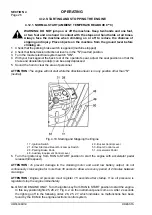
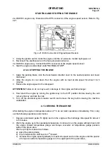
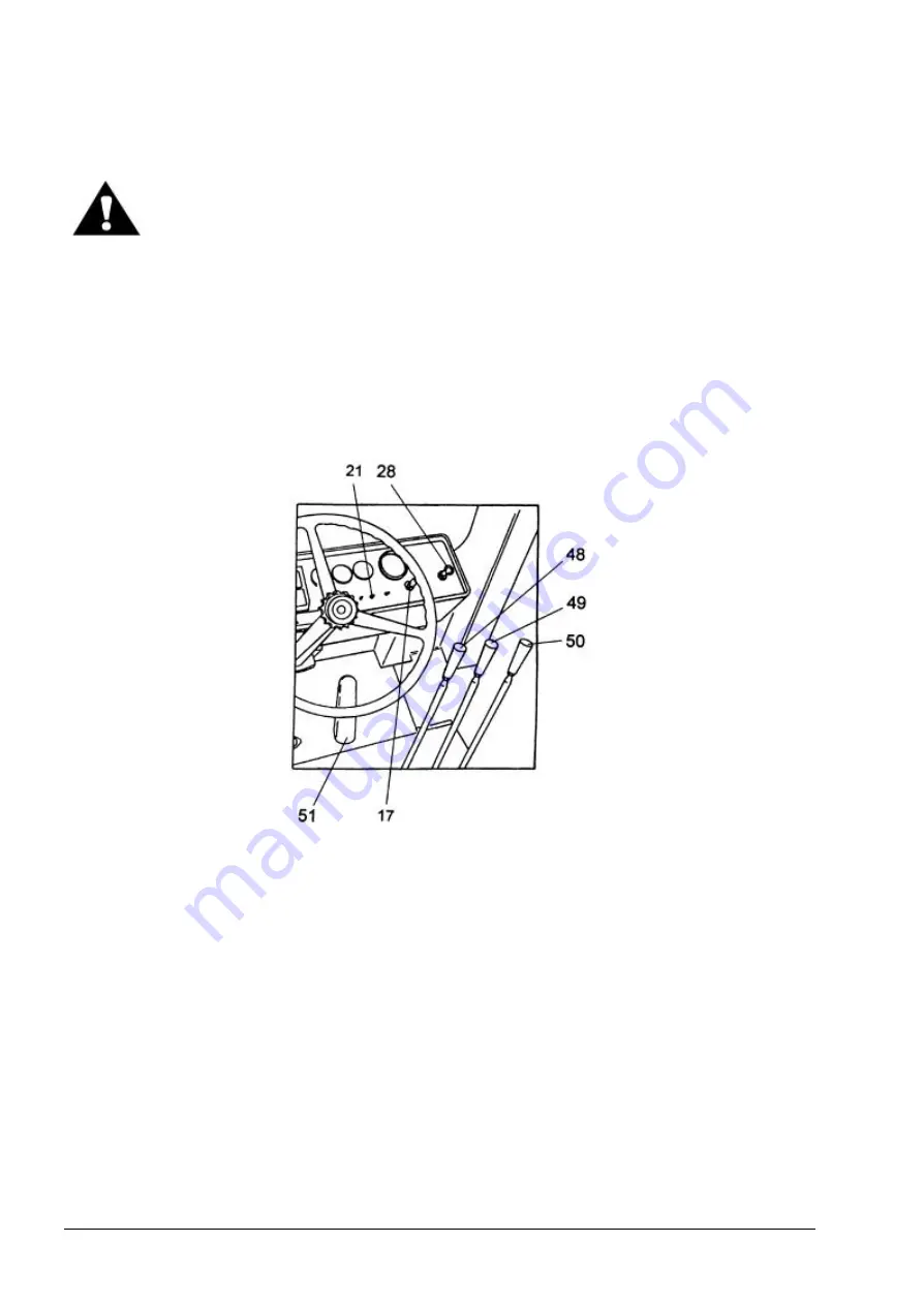
Fig. 4.19. Starting and Stopping the Engine
17 - Ignition Switch
21 - Ether Start and Rear Work Lamps Switch
28 - Parking Brake Knob
48 - Auxiliary Equipment Control Lever
49 - Bucket Control Lever
50 - Boom Control Lever
51 - Accelerator Pedal
6. Turn the ignition key from RUN to START position to start the engine with accelerator pedal
released (idle speed).
ATTENTION:
To prevent damage to the cranking motor and avoid low battery output, do not
continuously crank engine for more than 30 seconds. Allow a recovery period of 2 minutes between
crankings.
ATTENTION:
Engine oil pressure must register 15 seconds after startup. If no oil pressure is
registered stop the engine immediately.
6a. QSK 19C ENGINE ONLY. Turn the ignition key from RUN to START position to start the engine.
In this key position lights 25, 26, 27, Fig. 4.2. on the instrument panel come on. After 2 seconds
the lights go off in the following order: 26, 25, 27, which indicates no malfunctions has been
found by the ECM in the engine electronic control system.
Summary of Contents for 560C
Page 1: ...OM560C99 1E OPERATOR S MANUAL 560C SERIAL NUMBERS 15001 AND UP ...
Page 3: ......
Page 5: ......
Page 7: ......
Page 10: ...SECTION 1 INTRODUCTION ...
Page 12: ......
Page 16: ...SECTION 2 SAFETY PRECAUTIONS ...
Page 18: ......
Page 32: ...SECTION 3 MACHINE TRANSPORT AND STORAGE ...
Page 34: ......
Page 42: ...SECTION 4 OPERATING ...
Page 43: ......
Page 45: ......
Page 49: ...SECTION 4 OPERATING Page 6 OM560C99 1E DRESSTA UNIVERSAL SYMBOLS FOR INSTRUMENTS AND CONTROLS ...
Page 88: ...SECTION 5 MAINTENANCE ...
Page 141: ...SECTION 6 SPECIFICATIONS ...
Page 143: ......

