SECTION 4
OPERATING
Page 36
OM560C99/1E
DRESSTA
LOADER OPERATIONS
Adjustment of automatic boom kick-out
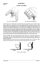
To change the automatic boom kick-out position, raise the boom arms to the desired stopping
height (factory set stopping height is maximum boom height). Loosen the bolt holding bar 2 in place
and slide it in bracket 3 so as it is positioned directly in front of proximity switch. Tighten the bolt
holding the bar. Start the machine and test the adjustment. Repeat this procedure until the
automatic kick-out height is obtained.
WARNING! Use extra caution when adjusting loader’s bucket leveler or boom
kick-out. Use two trained people and guard against accidental movement of the
machine or loader linkage. No personnel is allowed within the reach of loader
linkage. Never work or walk under raised bucket without proper blocking.
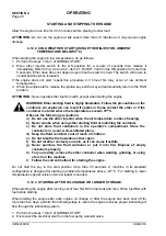
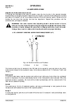
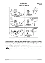
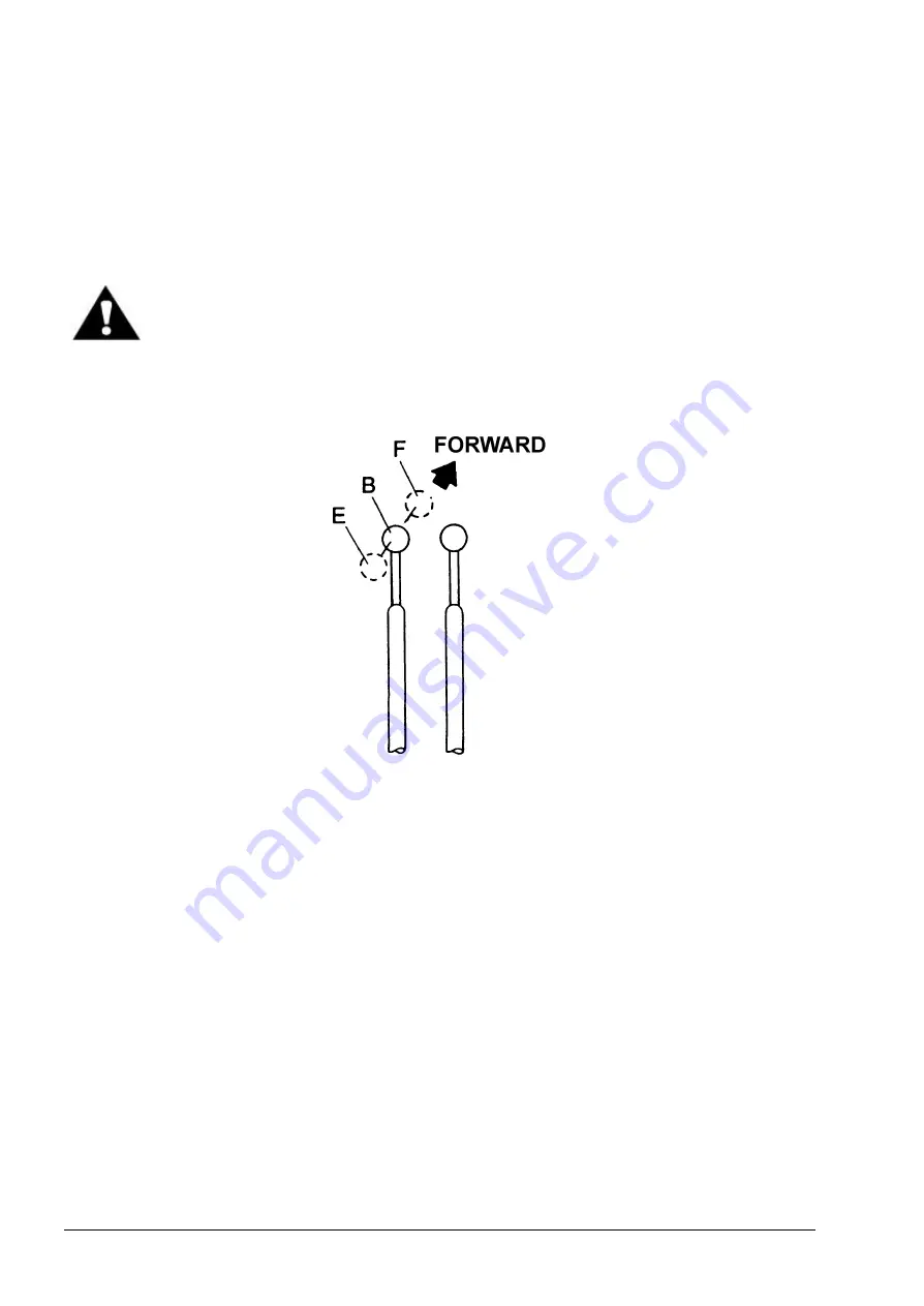
4.18.3. BUCKET CONTROL LEVER POSITIONS (FIGURE 4.27)
Fig. 4.27. Bucket Control Lever Positions
E. Rollback
B. Hold
C. Dump
The bucket control lever is situated on the RH side of the operator’s seat and close to the boom
control lever (closest to the operator's seat). It has three positions E, B, F ("roll back, "hold", and
"dump").
Roll back E
To roll the bucket back- load the bucket and pull the lever all the way back. When the automatic
leveler is inoperative, the lever automatically returns to the hold position when released. When the
automatic leveler is operative, the lever will be locked automatically with the solenoid latch. This
latch can be released manually.
Hold B
The control lever, if not in E detented position, will return automatically to hold position B when
released and will maintain the bucket in the required position.
Dump F
To dump the bucket, push the lever forward. When the lever is released, it will automatically return
to hold position B.
Summary of Contents for 560C
Page 1: ...OM560C99 1E OPERATOR S MANUAL 560C SERIAL NUMBERS 15001 AND UP ...
Page 3: ......
Page 5: ......
Page 7: ......
Page 10: ...SECTION 1 INTRODUCTION ...
Page 12: ......
Page 16: ...SECTION 2 SAFETY PRECAUTIONS ...
Page 18: ......
Page 32: ...SECTION 3 MACHINE TRANSPORT AND STORAGE ...
Page 34: ......
Page 42: ...SECTION 4 OPERATING ...
Page 43: ......
Page 45: ......
Page 49: ...SECTION 4 OPERATING Page 6 OM560C99 1E DRESSTA UNIVERSAL SYMBOLS FOR INSTRUMENTS AND CONTROLS ...
Page 88: ...SECTION 5 MAINTENANCE ...
Page 141: ...SECTION 6 SPECIFICATIONS ...
Page 143: ......


